1
\$\begingroup\$

I was inspecting my work with my first PCB in KiCAD.

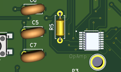
I was looking at the 3d model, and I was checking out the three decoupling capacitors I have placed.

I noticed that they do not actually connect with an IC (no trace.)

enter image description here

Of course, I made sure I routed all the ratsnest properly - and there are zero unrouted.

These capacitors, like I said are decoupling capacitors.

This means one pin is connected to Vdd and one to GND of the IC.

The Vdd of all the ICs is the front copper plane (5V) and the GND of all the ICs is the back copper plane.

My capacitors connect to the front copper plane and the back copper plane and that's it. No connection to ICs.

But, since the ICs connect to these planes, in order to get their power and GND connections, the ratsnest check is satisfied, and that ratsnest is cleared.

But I see no actual connection of an IC to one particular decoupling capacitor!

Isn't this like now there are three 100nF capacitors in parallel between the Vdd and GND?

So isn't it like one 300nF capacitor that between the two planes, that all the three ICs share?

Have I done something wrong?

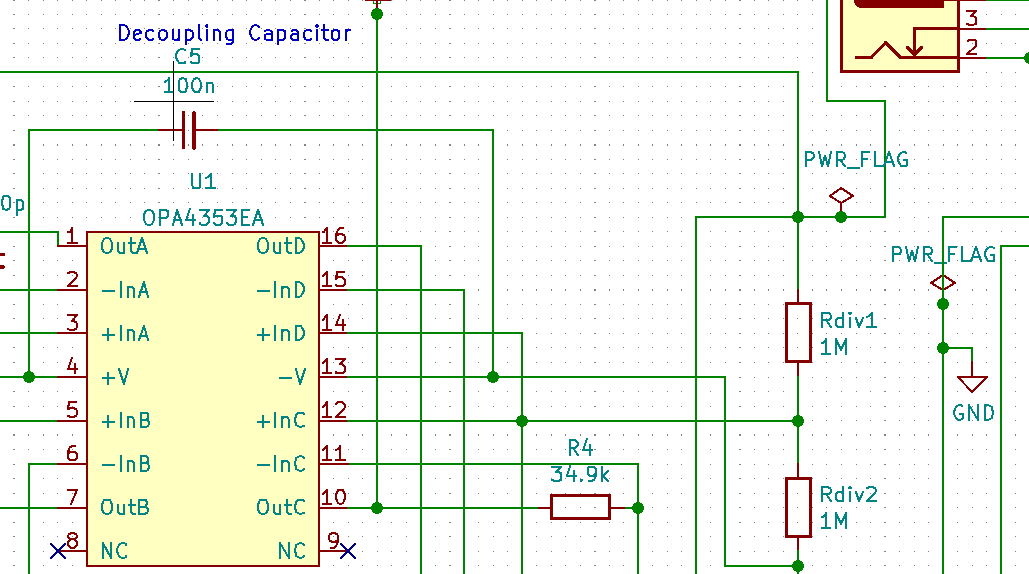
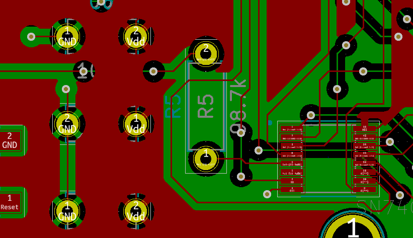
I also post picturess of the schematic as an example and the actual PCB.

enter image description here

enter image description here

\$\endgroup\$
1
  • 1
    \$\begingroup\$ Out of curiosity, why are you using big through hole components with SMD ones? Hand soldering an 0806 or 1206 component is pretty easy even for beginners. You are probably making your board more expensive than it needs to be... Some of your traces look to be extremely small as well, was this auto routed? \$\endgroup\$
    – Ron Beyer
    Commented Jan 8, 2021 at 1:01

2 Answers 2

6
\$\begingroup\$
  1. Decoupling caps should be physically close to the chips they decouple. Like, right next to them.
  2. KiCad doesn't have the smartest autorouter.
  3. Consider laying out the power traces by hand before letting the autorouter have its fun.
  4. KiCad will let you establish net classes; this, in turn, will let you define the traces on 5V to be thicker.
  5. Something about the way KiCad is set up, or what you're doing, is making it route a trace and then pour the planes. That's cutting up your 5V plane. It's been a while, but I think you can pour the planes first, and then autoroute, and then recalculate the planes (but that may be Eagle -- it's been a while).
\$\endgroup\$
3
\$\begingroup\$

Have i done something wrong?

Yes, you put the capacitors in the wrong place. They're decoupling capacitors, you're supposed to put them up against the thing you're decoupling. Move them there. The software makes sure you implemented the circuit as you drew it, not that you put things in places that make sense, so you can pass the DRC but have a very badly laid out circuit.

In addition, it would be better to use SMD capacitors. Those long through hole leads needlessly add to inductance, plus they're huge which is going to make routing hard.

\$\endgroup\$
0

Your Answer

By clicking “Post Your Answer”, you agree to our terms of service and acknowledge you have read our privacy policy.

Not the answer you're looking for? Browse other questions tagged or ask your own question.