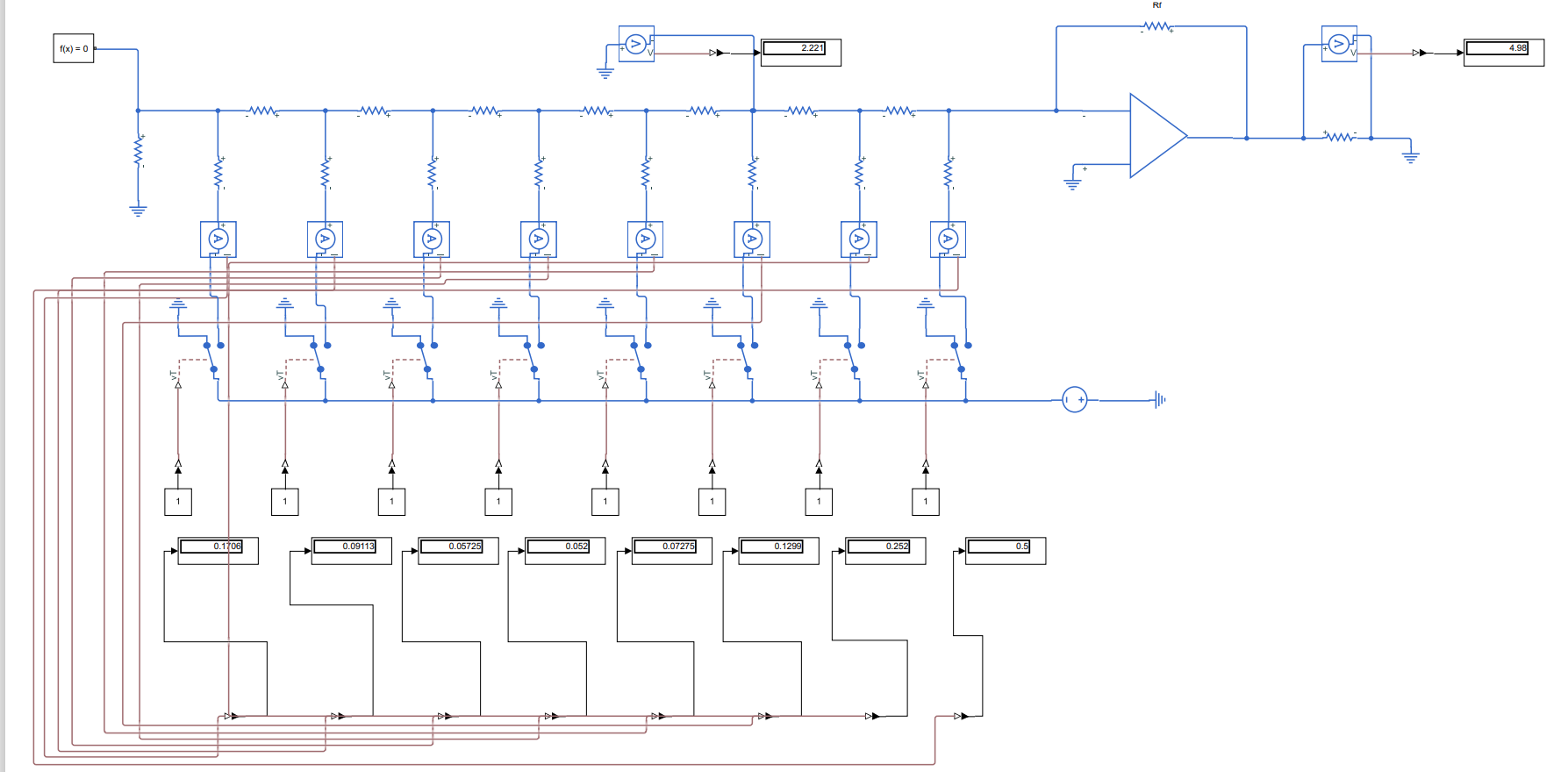
I'm really curious about the voltages at the nodes between the R resistors in the R-2R DAC ladder with an Op-Amp. I've tried using KCL and Ohm's law to find them, but I haven't been able to. Simulation shows different results.
The voltage source at the bottom is 3 V, in the ladder configuration, 2R resistors are vertical, and R resistors are horizontal.
R = 3 Ohm, 2R = 6 Ohm. Rf = 5 Ohm. The rightmost resistor is 1 Ohm.
One more thing to note, the switches seem to be on the ground, but when the simulation runs, I give it value of 1, and they are switched to the 2R resistors.
I've used the fact that the Op-amp has a "virtual ground" concept - when one terminal is grounded, so is the other. Therefore, the current through Rf resistor should be 4.98/Rf. The current through the rightmost 2R resistor should be just 3/2R, since one end is basically grounded. Then according to KCL, we have one current entering that node, and two currents leaving that node (one leaving to the 2R, the other leaving to the R). But this approach doesn't seem to be helping much. After a few nodes, the currents inthe ladder (and also the node voltages) stray really far away from my expected values. What am I missing here?

