2
\$\begingroup\$

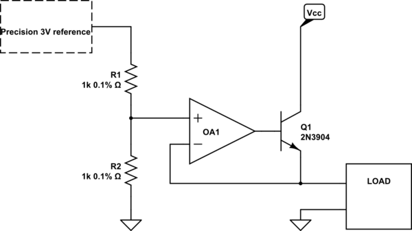
I'm designing a reference voltage generator for the analog section of a circuit. Two voltages as needed:

  • Vref = 3 V for ADC
  • Vref/2 = 1.5 V for signal conditioning circuits (with a load of about 40mA)

schematic

simulate this circuit – Schematic created using CircuitLab

The 3 V precision reference is already available, and I need an hint to generate a precision 1.5 V reference with a load of about 40 mA. In the schematic above, were are possible error sources? I can identify:

  • divider resistors tolerances
  • input current of OpAmp "+" pin
  • OpAmp offset
  • what else? I guess that BJT is in the high-gain loop of the OpAmp, so its finite gain and drifts should be automatically compensed. What do you think about?
\$\endgroup\$
17
  • 2
    \$\begingroup\$ Is noise an important consideration? What's the bandwidth under consideration? \$\endgroup\$
    – jonk
    Commented Jan 14, 2021 at 9:55
  • 2
    \$\begingroup\$ How much does the 40 mA load current vary in value? \$\endgroup\$
    – Andy aka
    Commented Jan 14, 2021 at 10:12
  • 1
    \$\begingroup\$ Flicker (1/f) noise might be an important consideration; there are amplifiers that do not suffer from it. \$\endgroup\$ Commented Jan 14, 2021 at 10:33
  • 2
    \$\begingroup\$ What is the Vcc? Do a calculation on the maximum current through Q1. How much power will Q1 then dissipate? Is that below its maximum? Will a heatsink be needed? Is the opamp's DC offset relevant? You're using 1% resistors, OK but you talk about precision, how much precision are we talking about? 1% (since you use 1% resistors). How accurate does your 1.5 V need to be? Is trimming allowed or needed? Precision doesn't mean anything unless you give numbers. Have a look at the datasheet of a TL431 and see how they specify precision. \$\endgroup\$ Commented Jan 14, 2021 at 10:53
  • 2
    \$\begingroup\$ If it's quite constant then why bother with the BJT - use a potential divider from Vcc to set the approximate voltage and let the op-amp output tweak that to be exactly 1.5 volts. An op-amp is good for +/- 5 mA without much hassle. \$\endgroup\$
    – Andy aka
    Commented Jan 14, 2021 at 11:00

1 Answer 1

1
\$\begingroup\$

If you stay with your current topology, one important thing to note is that the absolute precision of R1 and R2 basically doesn't matter (so long as you can disregard input leakage, which - for 1k - you can; and output impedance of your reference which you have not specified). What matters is the matching ratio between the two. If they drift by 20% and 20.0001% respectively your output will still be accurate. One easy (though expensive) way to pursue this is the use of an integrated divider with defined matching such as the Vishay ACA series with absolute tolerance of 0.1% but matching tolerance of 0.05%. If you pay a lot more you can get this to 0.01%. Since your question doesn't specify a final output tolerance it's not clear whether this is called for.

Your \$I_{CE}\$ is 40mA and \$V_{CE}\$ 1.5V. The BJT at approximately those conditions (50mA, 1V) has an \$h_{FE} \ge 60\$; for less current you'll have more gain (to a point). The op-amp needs to try and feed a small base current that will not saturate the BJT - based on figure 16 this will be less than 3mA. Such a low current should not see any adverse effect from the output impedance of the op-amp itself, though I'm not an expert in this area.

The one easily identifiable source of error (other than resistor tolerance) will be op-amp input offset, as you've identified. Offset trimming pins seem to have fallen out of favour so your best bet is a lasered pre-trimmed device. You say you need sub-700uV: this is fairly easy; these things go down to 100nV. The TI LM358B series has 300uV typ, and can operate on a 3V single-ended supply; or you can pay more for less offset.
\$\endgroup\$
2
  • \$\begingroup\$ Integrated divider, this is a very good idea. I need an accuracy of about 0.7mV (that is the LSB of a 12-bit converter fed by 3.0V reference). Do you see a source of uncertainty or error with the BJT? \$\endgroup\$ Commented Jan 18, 2021 at 21:56
  • \$\begingroup\$ Not really; it's in an "easy" region for the op-amp to drive. See edit. \$\endgroup\$
    – Reinderien
    Commented Jan 18, 2021 at 22:48

Your Answer

By clicking “Post Your Answer”, you agree to our terms of service and acknowledge you have read our privacy policy.

Not the answer you're looking for? Browse other questions tagged or ask your own question.