2
\$\begingroup\$

When a motor is already rotating, the rotor's mass and velocity carries a momentum and will continue to rotate in one or the other direction to align to the stator's magnetic field as the polarity of coil switches periodically.

Let's consider the simplest brush motor with only one pole as shown in the picture. If the rotor initially sits at rest in perpendicular to stator's magnetic field before current is applied, then once current is applied the rotor can either rotate clockwise or counter-clockwise to align to stator's magnetic field. The initial direction should be indeterministic (or 50% equivalent chance of rotating either clockwise or counter-clockwise).

How are those small DC motors always rotate in one direction unless we reverse supply's polarity?

initial direction of motor

[EDIT]
Most results I found on Google and videos on Youtube are self-contradictory or straight out erroneous.

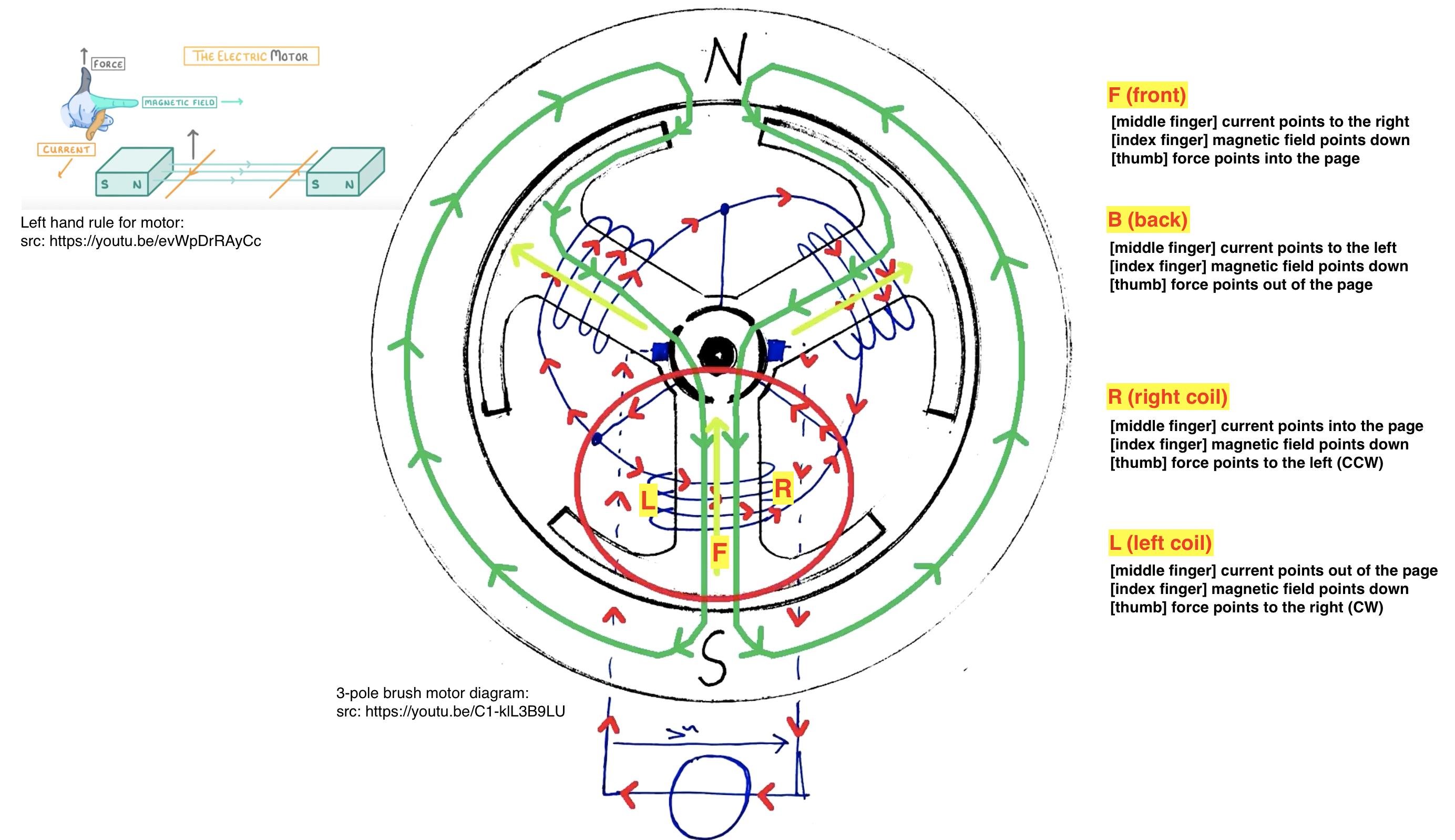
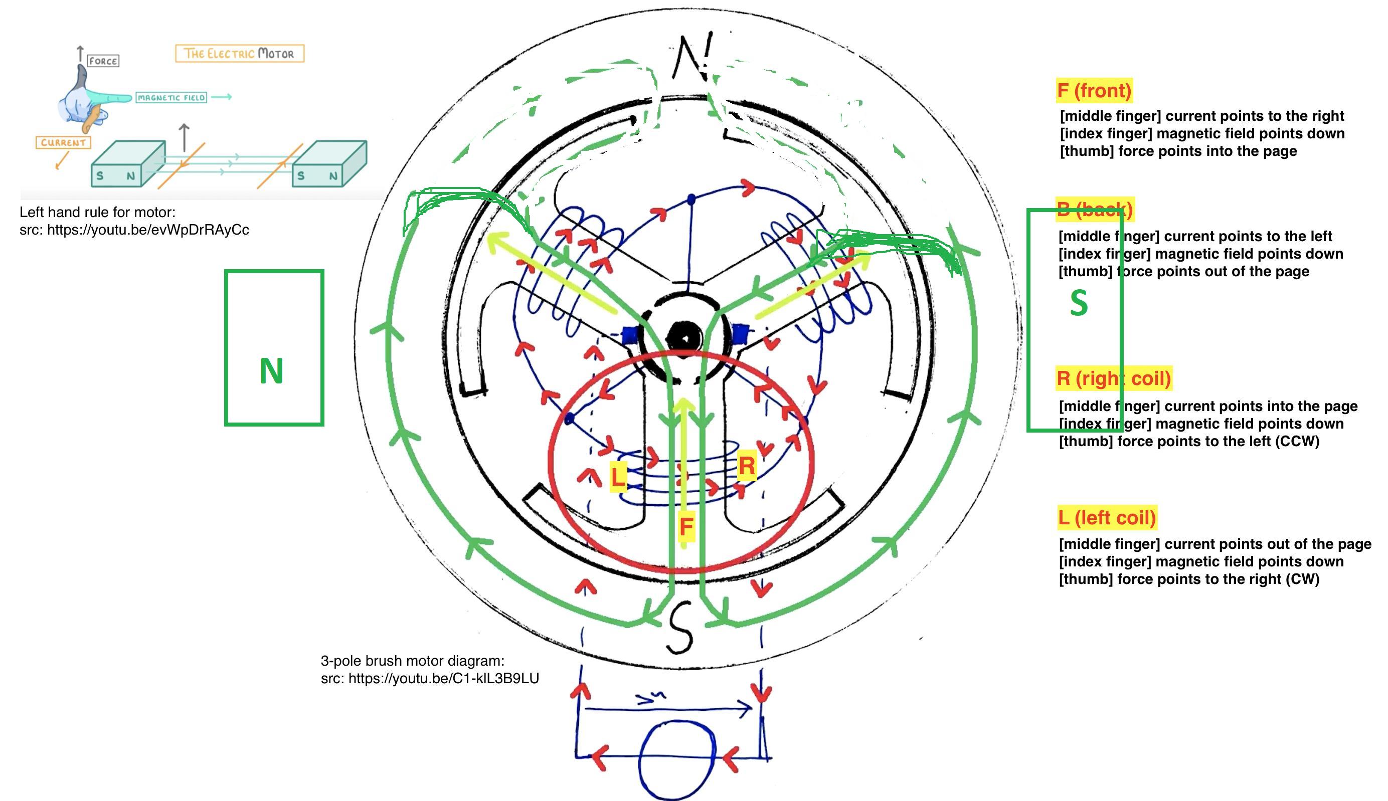
Here I provide the diagram for Fleming's left hand rule for motor and the cross section of a 3-pole brush DC motor, where the green arrow indicates the close path of the magnetic field, and right arrow indicates direction of a conventional current. The coil wrapped around the pole (circled in red) is subject to higher current than other two poles (hence the bias). The magnetic field generated by the coil (circled in red) opposes that from the stator (dark vs. light green arrow). Rotor has to rotate then - but to which direction?

  • If I apply the Fleming's rule, the force induced by the front section of the coil will get canceled out by that part of the coil that goes behind that pole. Coil on the right will have a force pushing to the left (CCW), canceling out the force pointing right (CW) from the left coil. It's easier to visualize it through the diagram along with description given for F, B, R and L - all induced Lorentz forces get cancelled in that coil that wraps around the directly energized pole!!

  • The only explanation I can see for why the rotor has to "move away" from its current position is because the magnetic field generated by the coil (lighter green) goes in opposite direction to that of the stator's magnet. But to which direction the rotor rotates away should be indeterministic. In other words, if I tab the rotor CCW with my finger right before current is applied, the motor will rotate CCW (because I give it that initial momentum), or vice versa for CW rotation.

motor diagram

\$\endgroup\$
7
  • \$\begingroup\$ are you certain that the motor you are asking about actually has the contruction you presented? \$\endgroup\$
    – jsotola
    Commented Jan 26, 2021 at 9:06
  • \$\begingroup\$ @jsotola you're right I realized I had the wrong picture \$\endgroup\$
    – KMC
    Commented Jan 26, 2021 at 10:37
  • \$\begingroup\$ Consider how to peddle a unicycle to go forward. You must be in sync with the rotor position when pushing on one side or the other. \$\endgroup\$
    – D.A.S.
    Commented Jan 26, 2021 at 12:01
  • \$\begingroup\$ Have you ever asked why a commutator is needed? It would be much easier to have slip rings, in such case you would get the problem that you are studying. A commutator switches between segments, so that the rotor field is always 90 degrees aligned to stator field. \$\endgroup\$ Commented Jan 26, 2021 at 12:17
  • \$\begingroup\$ @MarkoBuršič I understand how the switching keeps the current flowing in the same direction and hence the continuation of the rotation to that particular direction. But the question here is how the direction is determined at its start. Please see edit. \$\endgroup\$
    – KMC
    Commented Jan 26, 2021 at 21:34

3 Answers 3

4
\$\begingroup\$

How are those small DC motors always rotate in one direction unless we reverse supply's polarity?

For a DC motor with two commutator contacts (one rotor coil) the motor can run in any direction so let's clear up that first. What makes a practical DC motor run in the same direction all the time (for a given supply polarity) is that there are at least four commutator contacts and therefore two rotor coils. Let's deal with that situation.

The commutator brushes are positioned so that they only energize the rotor coil that is physically more biased to align its magnetic field with the stator magnets by rotating in (say) an anticlockwise way. So it begins moving anticlockwise to make an alignment.

90° of rotation later, the brushes are no longer driving the first coil because the commutator has rotated with the rotor; they are driving the 2nd coil and it's the same scenario. That new coil is physically more biased to align its (new) magnetic field with the stator magnets by rotating in the same anticlockwise way.

The process starts over.

More commutator contacts means more rotor coils and the angle at which the nth coil stops taking current and the n+1 th coil begins taking current becomes smaller. So, 8 commutator contacts means the rotor has 4 coils and changeover occurs every 45°.

\$\endgroup\$
4
  • 1
    \$\begingroup\$ Typically small motors have three commutator segments, not four, with three coils wired in a delta fashion. Even if they have more they will usually be an odd number with 5 being another common number of poles of the armature. The stator will usually have two poles. \$\endgroup\$ Commented Jan 26, 2021 at 18:07
  • \$\begingroup\$ I edited my question to emphasize on what what I'm questioning. I understand why the rotor rotates or why switching polarity keeps it going in a particular direction - but I don't see how a CCW or CW rotation can be "chosen" electromagnetically if without some external mechanical interference. I showed a 3-coil motor as @KevinWhite pointed out for simplification. \$\endgroup\$
    – KMC
    Commented Jan 26, 2021 at 21:48
  • 1
    \$\begingroup\$ It rotates initially in the correct direction because the brushes and the commutator positions only allow current to flow in the winding that creates the correct rotation for the applied electrical polarity. \$\endgroup\$
    – Andy aka
    Commented Jan 27, 2021 at 0:21
  • \$\begingroup\$ @KevinWhite amended to suit a hypothetical rotor with two quadrature coils. \$\endgroup\$
    – Andy aka
    Commented Jan 27, 2021 at 14:05
2
\$\begingroup\$

pai

Corrected the rotor flux lines and added the stator magnets. The commutator switches the rotor current so that rotor flux is always at right angle to the stator flux. More segments means better angle alignment, thus less torque ripple.

Extra animation here:

Animation

\$\endgroup\$
1
  • \$\begingroup\$ Thanks. And looking further into your animation (and similar others) I could pretty much sum up that while the Lorentz force (or the left hand rule) model explains the consistent CW/CCW rotation of a single coil, it contributes nothing to the 3-pole motor. The 3+ poles motor rotate straightly as a result of the magnetic field alignment where one pole always gets switched upon alignment and the other two poles attract and repel in a specific angle to push forth a specific direction and has nothing to do with left/right hand rule of Lorentz force. \$\endgroup\$
    – KMC
    Commented Jan 26, 2021 at 23:23
1
\$\begingroup\$

enter image description here

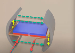
*Figure 1. In this position the rotor experiences maximum torque.

If the rotor initially sits at rest in perpendicular to stator's magnetic field before current is applied, then once current is applied the rotor can either rotate clockwise or counter-clockwise to align to stator's magnetic field.

No, if the rotor in Figure 1 is rotated 90° the torques are opposing and the net rotation is zero. That's why we use brushes to switch in another horizontal winding.

How are those small DC motors always rotate in one direction unless we reverse supply's polarity?

The brushes commutate (switch in) a winding that will be in the orientation shown in Figure 1.

\$\endgroup\$
3
  • \$\begingroup\$ I might have a misleading picture for the question. But imagine for an initial condition where the South of the rotor faces down (the rotor rotated 180 to that shown in the picture) then when coil current is applied the rotor would rotate the other way around instead (counter clockwise) because the stator's North is on the left. So the direction of rotation would depend on the initial condition of where the rotor is facing? \$\endgroup\$
    – KMC
    Commented Jan 26, 2021 at 10:45
  • \$\begingroup\$ The rotational force is due to the force on the current-carrying wire in the field, not the interaction between the stator and rotor magnetic fields. See the right-hand rule, etc. \$\endgroup\$
    – Transistor
    Commented Jan 26, 2021 at 10:50
  • \$\begingroup\$ Right hand rule: magnetic field points from N to S, or the righter commutator to the left (index), current going in on the left and out on the right (middle finger), the force induced (thumb) should be pointing down on the left or up on the right (counter clockwise) \$\endgroup\$
    – KMC
    Commented Jan 26, 2021 at 20:07

Your Answer

By clicking “Post Your Answer”, you agree to our terms of service and acknowledge you have read our privacy policy.

Not the answer you're looking for? Browse other questions tagged or ask your own question.