1
\$\begingroup\$

I don't quite understand how a buck converter works in terms of maintaining a constant voltage.

Let's say you have a 5V, 3A buck converter, but you hook it up to a 1K resistor (load) in series to give you a current draw of 5mA.

Now, let's say you start adding more 1K resistors in parallel to increase the current draw of the load(s).

What changes in the buck converter to meet the increase current demand?

Based on my understanding, there are only two parameters to play it here - switching frequency and duty cycle.

However, I thought that many buck converters have a fixed switching frequency, which rules that out as a possible parameter to tweak?

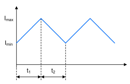
Part of my confusion comes from this graph shown in TI's power topologies handbook, where is shows the Imin and I max of the inductor current:

enter image description here

So my new hypothesis is that there is a part of the graph here that is not shown, which is the initial current rise from 0A to whatever the necessary current is to maintain the specified voltage drop.

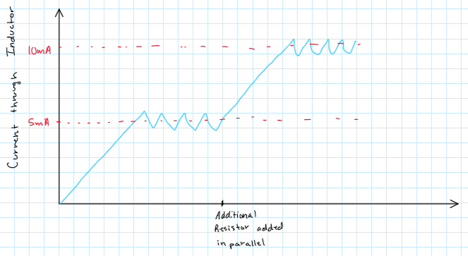
To answer my own question, what would happen if we started adding 1K resistors in parallel would be that there is a single instance/cycle where the switch stays closed for a longer time to allow the current through the inductor to ramp up to the necessary value in order to maintain the specified voltage drop across the load(s). See my crude drawing below:

enter image description here

\$\endgroup\$

5 Answers 5

2
\$\begingroup\$

I thought that duty cycle directly controlled the output voltage though? Wouldn't a change in duty cycle thus change the output voltage?

Duty cycle controls the steady state output voltage of a buck converter (for a fixed input voltage, in continuous conduction mode). So, for a fixed input voltage, why is a feedback loop even necessary? Part of the answer is that a fixed duty cycle buck converter will have transients, both when the input voltage is first applied, and also whenever the load changes. The feedback loop suppresses these transients.

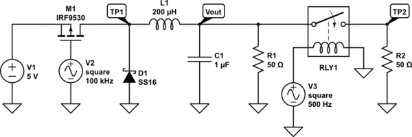
Here is a 50% fixed duty cycle buck circuit with a load that changes from 50\$\Omega\$ to 25\$\Omega\$ at 1ms. The supply is 5V.

schematic

simulate this circuit – Schematic created using CircuitLab

enter image description here enter image description here

As one can see, the steady state voltage is the same before and after the load changes, but there is a transient voltage swing that begins when the load changes. If there were a feedback loop, the switching contoller would temporarily increase the duty cycle when the voltage began to sag, but would return the duty cycle to 50% as soon as the capacitor/inductor pair stabilized at the new current level.

\$\endgroup\$
2
\$\begingroup\$

What changes in the buck converter to meet the increase current demand?

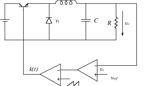
The duty cycle of the PWM signal (which controls the switching element) is changed such that the output voltage remains constant.

enter image description here

Picture found here.

In this picture, the PWM signal is marked k(t).

The error signal \$V_e\$ ( = \$V_{ref} - V_o)\$ is amplified and then used to influence the PWM signal.

What the actual shape of the current through the inductor looks like depends on the load current. Your drawing might be correct for many of those situations.

\$\endgroup\$
7
  • 1
    \$\begingroup\$ I thought that duty cycle directly controlled the output voltage though? Wouldn't a change in duty cycle thus change the output voltage? \$\endgroup\$ Commented Jan 27, 2021 at 10:12
  • \$\begingroup\$ I thought that duty cycle directly controlled the output voltage though? When the load is constant then yes, the DuCy would directly influence the output voltage. But the opposite is more useful, we keep the output voltage constant by changing the DuCy. For a constant load, that DuCy would remain constant. However you don't know what DuCy you need for a specific output voltage as that depends on the load. That's why the feedback loop is needed, to generate "whatever PWM signal is needed" to keep the output voltage at a specific value. \$\endgroup\$ Commented Jan 27, 2021 at 10:16
  • \$\begingroup\$ I think I understand what you're saying. A 10V output voltage across a 10 ohm load will require a different duty cycle than a 5V output voltage across a 5 ohm load, is that correct? \$\endgroup\$ Commented Jan 27, 2021 at 10:19
  • 1
    \$\begingroup\$ Yes/no, you're comparing 5V to 10 V. That's confusing as the DuCy is also related to the difference between input and output voltage. It is easier to state: A 1.0 Ampere load will require a different duty cycle than a 1.2 Ampere load (assuming everything else remains the same). \$\endgroup\$ Commented Jan 27, 2021 at 10:24
  • 1
    \$\begingroup\$ Yes, you're getting it :-) \$\endgroup\$ Commented Jan 27, 2021 at 10:30
1
\$\begingroup\$

Let's say you have a 5V, 3A buck converter, but you hook it up to a 1K resistor (load) in series to give you a current draw of 5mA

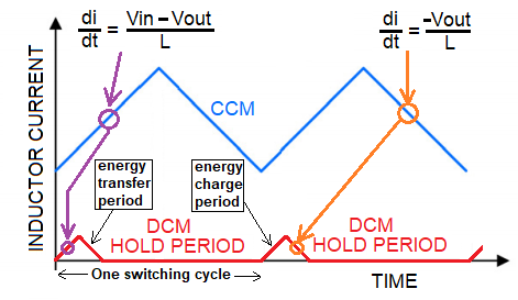
Then it's highly likely that the device will drop out of CCM (continuous conduction mode) and fall into DCM (discontinuous conduction mode) shown with the red waveform below: -

enter image description here

Looking at the red waveform, the inductor charge period is very much shorter. This is because the energy needed per cycle to sustain the output voltage with a 5 mA load is much smaller.

After it has charged the inductor, the stored energy quickly transfers to the load/output capacitor and then nothing happens until the cycle begins again.

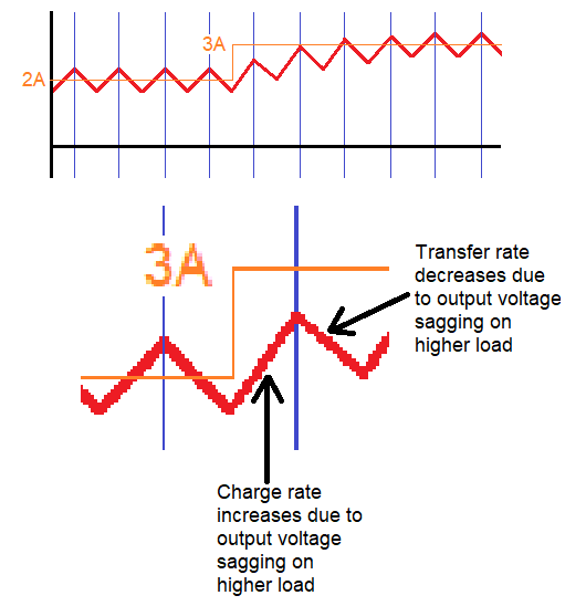
Regards how 2 amps might become 3 amps in CCM, here's what will likely happen: -

enter image description here

However, when going from 2 amps to 3 amps output (in CCM) there will be extra losses in the inductor, the diode and the switching transistor. These extra losses will result in a small increase in duty cycle brought about by the controller chip in order to achieve the desired output voltage.

\$\endgroup\$
7
  • \$\begingroup\$ Is my second graph a correct representation of what happens when you increase the load/current draw? \$\endgroup\$ Commented Jan 27, 2021 at 9:32
  • \$\begingroup\$ Given that the full load situation is 3 amps, it's highly likely that below (maybe 0.5 to 1 amp), the converter will drop into DCM and that has waveforms as shown in my picture (red). \$\endgroup\$
    – Andy aka
    Commented Jan 27, 2021 at 9:46
  • \$\begingroup\$ Buck converter wiki. \$\endgroup\$
    – Andy aka
    Commented Jan 27, 2021 at 9:49
  • \$\begingroup\$ Ok, let's say we are going from a load of 1A to 2A, would the graph I drew be correct? \$\endgroup\$ Commented Jan 27, 2021 at 9:50
  • 1
    \$\begingroup\$ Extra drawing added @RGBEngineer that shows the change in current from 2A to 3A. \$\endgroup\$
    – Andy aka
    Commented Jan 27, 2021 at 10:14
0
\$\begingroup\$

I'm no expert on this matter, so it's my private opinion based on some understanding of the stuff. Please, correct me if necessary.

All the components in that circuit have some sort of resistance (or dynamic impedance more like), which means as you draw more current, you will have more voltage drops everywhere, which the circuit will have to compensate for. Output a tiny bit extra to cover for voltage losses (let's not forget every every buck converter includes a voltage divider with negative feedback loop to monitor and adjust its own output voltage - it senses its own output in a way). Add to that thermals, which can have various effects on the components, including their impedance, inductance etc.

I would recommend EEVBlog's video about Linear and Switching converters, as well as Operational Amplifier video of his (this one first). He covers feedback and how the regulators sense their own output and adjust to maintain constant output voltage with changing conditions (current, temp, etc.).

\$\endgroup\$
0
\$\begingroup\$

As you well say if the frequency is fixed the buck converter will change the duty cycle.

The graf you're mentioning is relative to a costant load. In case the load change the discharge ramp will change the slope and can became longer or shorter depending if the load is decreased or increased.

The duty cycle will compensate the change as on the input the slope will still be the same (the load is the inductor).

So when the load decrease t1 will decrease as well, t2 will increase while the decreasing slop will became more flat.

\$\endgroup\$
2
  • \$\begingroup\$ I thought that the duty cycle affect the output voltage though? If that is true, then changing the duty cycle would not work because we are trying to maintain a constant voltage while increasing the load/current draw. \$\endgroup\$ Commented Jan 27, 2021 at 9:30
  • 1
    \$\begingroup\$ @RGBEngineer You are looking at it too one dimensionally. It relies on the increased load to bring the voltage back down. When you drain a cap you increase the current and as they drain the voltage drops. Right now you are thinking something along the lines of "if I push something harder it MUST speed up, while forgetting the fact that if what you are pushing has weight added to it, it doesn't speed up and can even slow down. Understand that those graphs an things you are looking at are simplifications with assumptions about the conditions, but there is a control system underneath. \$\endgroup\$
    – DKNguyen
    Commented Jan 27, 2021 at 13:53

Your Answer

By clicking “Post Your Answer”, you agree to our terms of service and acknowledge you have read our privacy policy.

Not the answer you're looking for? Browse other questions tagged or ask your own question.