I am building a spot welder for attaching nickel strips to Li-Ion cells to make custom battery packs. There are plenty on the market but I wanted to use up some components and learn something.
The idea is I'll use a foot pedal to trigger an MCU to pulse a large array of FETs for a configurable amount of time, and then enforce a 1 sec cooldown period. The FETs effectively short the battery across the welder probes for this brief period of time, probably a few milliseconds but I'll have to experiment there.
The lab is here: https://www.circuitlab.com/circuit/sfms963nw44y/gate-drive-lab-for-spot-welder/
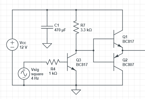
The driver schematic:
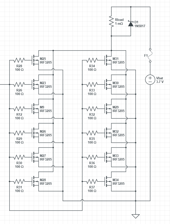
The FET array:
I am not an electrical engineer so I am asking for help figuring out if my circuit is sound. It's pieced together from many different online sources covering the various concerns that go into the project. I am not providing the full KiCad for the PCB because it's not done yet, I will come back and edit to add it here.
Design Goals:
- Use a hobbyist MCU (going to try out the new RPi Pico)
- Minimize pulse times to avoid injecting heat into the cell
- Big discharge current, shorter pulse times
- Slam the FETs open and closed as quickly as possible to try to avoid the magic smoke
Other project goals:
- Build the gate driver out of discrete components for educational purposes
My questions:
- Is R7 sized appropriately? Not sure what the considerations are here.
- Any sizing considerations for the push-pull BJTs? The lab seems to think that the current will be measured in microamps--but I found that quite surprising, as the point is to pull the gates high and low as quickly as possible.
- Is there something I should do to isolate the controller from the rest of the circuit?
- Are the gate resistors sized appropriately? I couldn't seem to find a straight answer on how to size these things, and they appear to be necessary to make the FETs all work in unison.
Misc Notes:
- D1 will be 82CNQ030 (Schottky, 30V, 80A), I didnt see a comparable diode in Circuitlab
- The I haven't figured out how to size the F1 fuse yet
- Vsig represents a 3.3 GPIO pin
- Rtest will not be in the final circuit
- I am software developer by trade, with only hobbyist level knowledge of circuit design


