For context: I am looking to step up 12V AC at ~25Hz to ~75V. Required output current is no more than 3W.
I'm looking for a small PCB mountable transformer which would do this job. I think that I understand the basic premise of transformers and that the ratio between the primary and secondary coils should be somewhere in the region of 1:6 to achieve this step up.
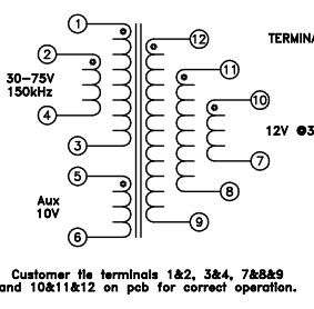
I've been looking at a variety of Flyback transformers such as this one: https://docs.rs-online.com/40b2/0900766b810a6c6a.pdf. The datasheet has a diagram as follows:
This implies to me that there are 3 primary and 3 secondary coils. I am presuming this is to allow for a variety of ratios to be used, as required. However, it is not at all clear from the datasheet what those ratios are.
The datasheet seemingly gives some example turn ratios:
Though these seem somewhat incomplete. My questions are:
- Am I reading this diagram correctly? Are there indeed 3 coils on each side?
- How do you go about determining the number of turns on each coil?
- The datasheet says the ratio of 1-3:5-6 is 2.8:1. How is this possible? Looking at the diagram, those coils seem to be both on the same side of the transformer
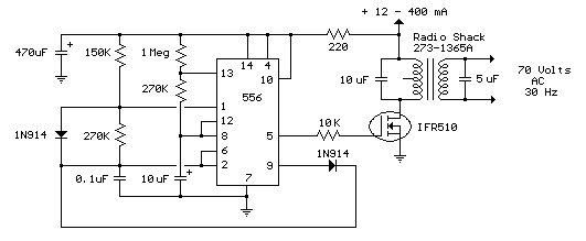
Edit: It’s feasible this is an X-Y problem and there’s a better solution. I’m looking to make a ring generator for an old analogue phone. I have a prepackaged unit made by PowerDSine but as a learning exercise it seemed interesting to make one. Sample circuit I’m working off is below. I have a 12V input and a 555 + RC filter generating a decent sine wave at the frequency I want - I figured I could feed it into a couple of MOSFETs and then step up to 75v.


