2
\$\begingroup\$

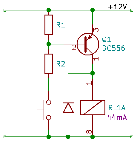
I am new to electronics. I am trying to figure out voltage divider to bias a transistor in saturation mode to drive a relay coil. Here's the circuit:

enter image description here

The coil resistance is 270 Ω. So the collector current has to be 44 mA. With hfe = 110, Ib = 0.4 mA. So R2 = 12V / 0.4 mA = 30 kΩ. Vb has to be lower than Ve by 0.7V. Let's say 11V. So R1 = 3.3 kΩ. Am I correct so far?

Also in some tutorial it says "The amount of biasing current flowing through resistor R2 is generally set to 10 times the value of the required base current IB so that it is sufficiently high enough to have no effect on the voltage divider current or changes in Beta." What does that mean exactly?

\$\endgroup\$
1
  • 1
    \$\begingroup\$ No. " in saturation mode" means, take hfe=10 (or 20 if you're really short on power). So R2 = 3k. And you only need a sniff of current to turn Q1 off so R1 can be 10k or higher ... just swap your resistors over! \$\endgroup\$
    – user16324
    Commented Feb 4, 2021 at 22:47

2 Answers 2

5
\$\begingroup\$

They are saying that you should have Ic/Ib ~= hFE/10 or about 11 in this case.

You want to drive the transistor deep into saturation to minimize the voltage drop across it, not provide the minimum current that (under nominal conditions) might drop a volt or two across the transistor. When fully saturated, there should be a much lower drop.

The current through R1 is subtracted from the base current, so R2 must provide even more current in order to feed both.

So, let's say we want Ib = 4mA, that means that R2 must be less than (12-0.7)/0.004 = 2.83K.

R1 is used to ensure the transistor turns off fully so, you might want to make it such that the current through R1 is 1/20 of the base current, or 200uA. So R1 = 0.7V/.2mA = 3.5K (maybe you use 3.6K as a standard value).

Now R2 has to supply 4.2mA so it will be (12-0.7)/0.0042 ~= 2.7K

Note: The value of R1 above is very conservative for most situations. To get an actual maximum value you'd have to calculate the leakage from Icbo and gain at the maximum operating temperature. Even with R1 infinite it will typically leak only a few uA through the relay coil at the maximum junction temperature. You might also want to consider leakage across the switch etc. so 100K or so would probably take care of that unless you're expecting a flood. I'd probably use 10K.

\$\endgroup\$
2
  • \$\begingroup\$ Thanks a lot. I understand now.Only i think you meant R2 in the last sentence. \$\endgroup\$
    – Viktor
    Commented Feb 4, 2021 at 22:52
  • \$\begingroup\$ Correct, changed now. \$\endgroup\$ Commented Feb 4, 2021 at 22:59
2
\$\begingroup\$

"Also in some tutorial it says "The amount of biasing current flowing through resistor R2 is generally set to 10 times the value of the required base current IB so that it is sufficiently high enough to have no effect on the voltage divider current or changes in Beta." What does that mean exactly?"

The DEFINITION for saturation requires that the base-collector pn junction is forward biased. So - how we can be sure that this condition is realized?

Answer: The current into the base node now must consist of two currents: The "normal" current to the emitter and - in addition - the current to the collector.

Therefore, the current into the base must be much larger than under linear operation conditions (amplification). And as a kind of "rule of thumbs" we require: The base current Ib should be at least one tenth of the collector current (which is 10 times larger than for linear opeeration, assuming a specified value B=100).

Hence, a maximum ratio of Ic/Ib=10 is a good and safe INDICATION for saturation.

\$\endgroup\$
1
  • \$\begingroup\$ Thanks for the explanation. \$\endgroup\$
    – Viktor
    Commented Feb 5, 2021 at 13:30

Your Answer

By clicking “Post Your Answer”, you agree to our terms of service and acknowledge you have read our privacy policy.

Not the answer you're looking for? Browse other questions tagged or ask your own question.