1
\$\begingroup\$

I have a AC sine/triangle wave I want to represent with single red/green LED. When positive side goes up then green light increases and opposite for negative/red light. This is pretty simple with two separate LED's, but I'm not sure at all how to go about this with RGB LED that has common anode/cathode. There are two big issues to solve:

  1. There is dead zone area where voltage is too low to trigger the LED.
  2. Perceived brightness curve is not linear, it takes more power to make it brighter each step. So it probably needs some kind of linear to exponential response.

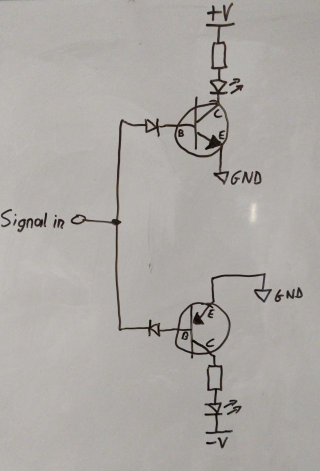
I managed to make this with separate LED's:

enter image description here

\$\endgroup\$
7
  • 1
    \$\begingroup\$ tinyurl.com/y2p88reg \$\endgroup\$
    – dandavis
    Commented Feb 12, 2021 at 14:49
  • \$\begingroup\$ Thank you for the schematic. I guess I didn't make it clear enough that I want the LED to dim. \$\endgroup\$ Commented Feb 12, 2021 at 14:52
  • \$\begingroup\$ it needs resistors anyway, and it will dim once built, that was just the basic idea... \$\endgroup\$
    – dandavis
    Commented Feb 12, 2021 at 14:53
  • \$\begingroup\$ Oh ok, I think I get it. Thou your schematic has two wire signal. But I have one wire that oscillates from - to +. \$\endgroup\$ Commented Feb 12, 2021 at 14:59
  • \$\begingroup\$ A problem you might consider: our eyes sense "intensity" in a non-linear way. That is, the impression of "bright" -to- "very bright" requires a much larger LED current increase than going from "very dim" -to- "dim". So translating a bipolar input voltage to LED intensity requires a non-linear transfer function. \$\endgroup\$
    – glen_geek
    Commented Feb 12, 2021 at 15:14

3 Answers 3

3
+100
\$\begingroup\$

Really cool problem :)

Regarding your first question, you would need a circuit which has a kind of bend when your signal input is around 0V. You can do this by adding diodes in the feedback of an operational amplifier. Something like this:
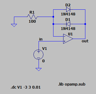
enter image description here

The output function of the circuit looks like this:
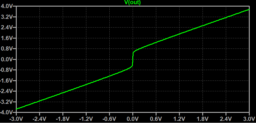
enter image description here

Note that R1 is needed to have a proper load for the diodes. By decreasing R1 you increase the forward voltage of the diodes and therefore the "height" of the bend region. You can also add aditional diodes to increase the bend region without increasing the diode current.

Regarding your second question. You need something which transforms your linear input voltage to an exponential output current. Fortunately a BJT does exactly this. Leading to a circuit like this: enter image description here
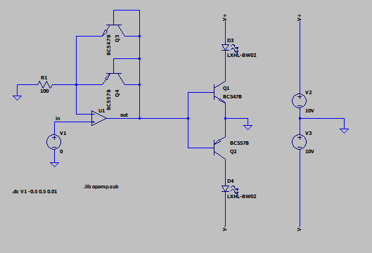
Please note I replaced the diodes with the BJTs in a diode configuration to have a similiar UBE in the amplifier feedback.

The current through the LEDs looks like this: enter image description here
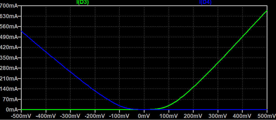
It seems that the exponential behaviour of the currents becomes more linear with higher input voltages. So maybe this is only suited for small input voltages.

Hope this helps :) Have fun :D

EDIT:

@somerandomusername: I just reread your problem and I totally overlooked that you wanted to use a common-anode or common-cathode LED. To solve this you can simply add an inverting amplifier with a gain of -1. And as user69795 suggested: if you only need a linear increasing LED current you can just add a resistor in the emitter of the BJT as a current feedback. The current through the LED will be roughly: \$ I = \frac{U_{out} - U_{BE}}{R_E} \$

This leads to a circuit like this:
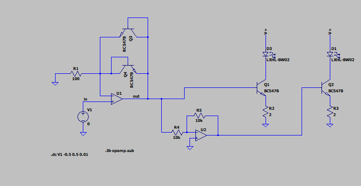
enter image description here

\$\endgroup\$
7
  • \$\begingroup\$ I believe somerandomusername may be incorrect in thinking he needs exponential gain. Since the brightness of a led is linear with current, your first op amp solution ( with led’s in place of the diodes) is most likely exactly what he wants. This will make the led’s brightness linear with the triangular input waveform’s voltage. \$\endgroup\$
    – user69795
    Commented Feb 15, 2021 at 21:52
  • \$\begingroup\$ Thank you for the effort. I will try to understand what is happening here. I came up with a solution on my own, check it out and please give me some critique \$\endgroup\$ Commented Feb 17, 2021 at 9:38
  • \$\begingroup\$ @user69795 well the brightness might be linear, but from my own observations the perceived brightness is not. It is really easy to tell the difference when LED goes from 10% to 20%, but really hard to perceive change from 80% to 90% \$\endgroup\$ Commented Feb 17, 2021 at 9:45
  • \$\begingroup\$ So I built the schematic and this is the result I got: i.imgur.com/gzgzhSv.png . Top and bottom is cut off, but I can fix it by increasing R1 to ~600. Is there a way to increase that dead zone? now it is -400mV to +600mV and that is not enough to start the LED. \$\endgroup\$ Commented Mar 1, 2021 at 10:19
  • \$\begingroup\$ I could add a voltage divider on the signal before going in, and then 3x the output with another opamp, that could increase the "dead zone" \$\endgroup\$ Commented Mar 1, 2021 at 10:28
1
\$\begingroup\$

If this is a fairly low-frequency wave you want to represent, you could sample your waveform with a microcontroller ADC, then convert the waveform voltage to separate green LED and red LED PWM outputs. Then you have control over the visual effect, including doing a non-linear (gamma) mapping to improve the visualization of voltage.

Why non-linear mapping? The LED brightness (luminance) will be linear with its current (or average current if PWM is used). But the perceived brightness to the human eye will have a logarithmic relationship to current.

In broad terms, the eye is more sensitive to changes in intensity at low light levels than it is at high light levels, so gamma mapping applies an inverse curve to compensate for that.

More about gamma here: https://www.cambridgeincolour.com/tutorials/gamma-correction.htm

You will also need an input circuit to level-shift and normalize the input to the ADC range.

I know this sounds complicated, but note that you could do this with a single 8-pin uC like ATTiny and a dual op-amp package. This could be made small enough to fit in a pen and cost less than a dollar.

\$\endgroup\$
1
  • \$\begingroup\$ Thank you for the input. I came up with a solution similar to your suggestion using PWM, but without the microcontroller. And the pulse width gets wider the higher it goes, helping with the perceived brightness issue. \$\endgroup\$ Commented Feb 17, 2021 at 9:47
1
\$\begingroup\$

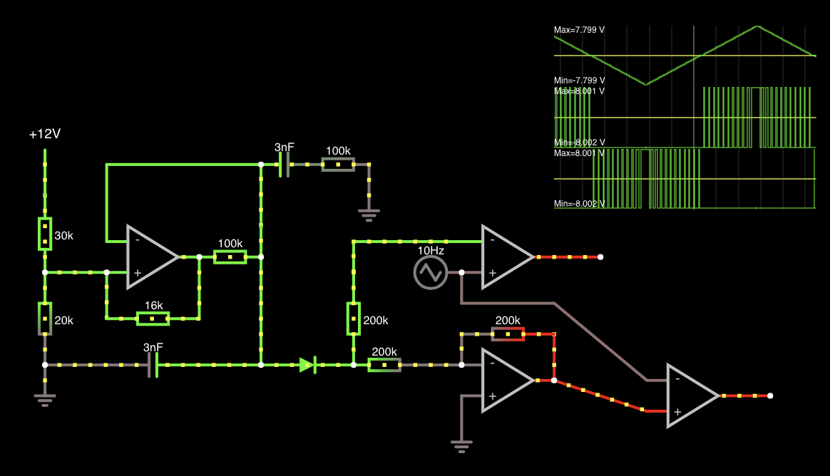
Thanks for all the help. I will definitely check out the solution @ringk89 came up with. I had idea of my own, trying to solve this using PWM. This is the solution I came up with:

enter image description here Simple sim: falstad sim

It is somewhat exponential, and I have tested (without the inverter so far) it on a breadboard and it seems to work great. Values are a bit different as this simulator is not accurate.

\$\endgroup\$
2
  • 1
    \$\begingroup\$ Cool idea and cool tool, I didn't know falstad so far :) \$\endgroup\$
    – ringk89
    Commented Feb 17, 2021 at 16:37
  • 1
    \$\begingroup\$ It looks fine to me and if the circuit works on a breadboard then it obiviously works :D my only recommendation is to maybe add a MOSFET or a BJT to drive the LEDs. Sometimes operational amplifiers can't source enough currents for LEDs (or at least not for long). But this highly depends on your LEDs and the operational amplifiers. \$\endgroup\$
    – ringk89
    Commented Feb 17, 2021 at 16:43

Your Answer

By clicking “Post Your Answer”, you agree to our terms of service and acknowledge you have read our privacy policy.

Not the answer you're looking for? Browse other questions tagged or ask your own question.