0
\$\begingroup\$

I have two components in a circuit: An Arduino Uno R3 and a Wind Sensor Rev. P. See diagram below. The wind sensor requires 12V to operate, so I powered it with an external power supply (provides 12V DC at 1A). The wind sensor outputs an analog signal up to 5V with the sensor reading.

I would like to use my arduino's analog-to-digital converter to read the sensor value. But can I do this if the arduino is powered with a different power supply? I have it connected to my laptop with a 5V USB cable.

I tried reading the value but I get fluctuating readings. To debug, I made a few more connections from the analog-in pins. As seen in the diagram, I can read voltages correctly if they are from the arduino. But if I try to read any voltage from the external power supply, the value is random.

I used a multimeter to check the voltages in the external power supply are 11.20V (close enough to 12V) and the voltage from the sensor OUT pin is 1.40V (within the 0V - 5V range I expected).

So why can my arduino not measure these voltages? I assume it's because the two different power supplies are changing the frame of reference for the ADC pin. But it's not clear to me, so I would appreciate a conceptual explanation.

My intuition tells me that both power supplies should share the same GND pin. But I didn't want to connect the GND between the two power supplies together, given they operate at different voltages and currents. Is this safe to do? Or should I just get a power supply module that will allow a single power supply to output both 12V and 5V?

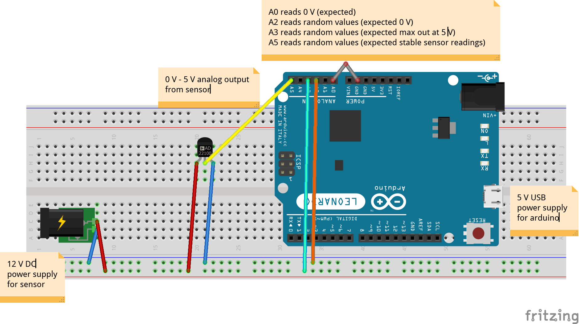
circuit schematic

\$\endgroup\$
3
  • 1
    \$\begingroup\$ Trust your instincts. If the power supplies both isolated from high voltage nothing wrong to connect grounds. \$\endgroup\$
    – user263983
    Commented Feb 21, 2021 at 21:41
  • 1
    \$\begingroup\$ Ground means 0V where you choose it and all the 0V points must be common with good decoupling caps on Vdd close to the devices. When you measure V with a DMM are you aware of the impedances involved and noise ? This makes a difference to the Arduino. \$\endgroup\$
    – D.A.S.
    Commented Feb 21, 2021 at 23:42
  • \$\begingroup\$ Always verify all grounds read 0V and Supplies are correct . You were probably pulling down by ESD diode drop. to get 11.20 Is that really within spec of the regulator? \$\endgroup\$
    – D.A.S.
    Commented Feb 21, 2021 at 23:49

1 Answer 1

1
\$\begingroup\$

You can and must connect the grounds together. It's the common reference. The only other thing wrong with your Fritzing picture is that you are feeding the ADC 12V voltage, divide it down with a simple voltage divider with two resistors. You don't need to measure the GND with the ADC.

\$\endgroup\$
1
  • \$\begingroup\$ Thanks, this works! I was worried about connecting grounds because my external power supply provides 1.25A, but the arduino only handles 800mA. Now I realize this is totally OK, the arduino will just draw as much current as it needs. \$\endgroup\$
    – nareddyt
    Commented Feb 26, 2021 at 5:27

Your Answer

By clicking “Post Your Answer”, you agree to our terms of service and acknowledge you have read our privacy policy.

Not the answer you're looking for? Browse other questions tagged or ask your own question.