0
\$\begingroup\$

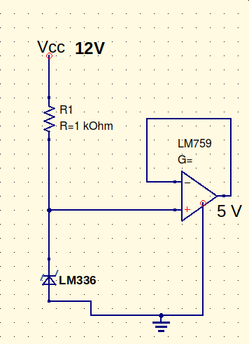
I would you to help me to understand a circuit I have in my notes which is reported in the following picture.

enter image description here

First of all it's my first time in which I see the supply voltage in some ways connected to one of the opamp inputs, which looks a little bit weird to me. Secondly I would expect a 2.5 V as output voltage instead of the 5V reported here.

In fact, according to my knowledge, the opamp is in a kind of non inverting configuration, where the gain should be

\$ G = 1 + \frac{R_g}{R} \$

since \$R_g\rightarrow 0\$ and \$R\rightarrow \infty\$ then the gain is \$G = 1\$.

Furthermore the LM336 has a breakdown voltage of 2.5 V, honestly I am not sure the voltage drop is large enough to guarantee a breakdown configuration, but I don't see any sense in putting a Zener diode in confinguration which is not the breakdown one.

From these considerations, I argue that the opamp, with its gain \$G = 1\$ provides a stable tension of 2.5 V in its output, and that the current passing through R should be \$(12V-2.5V)/1k\Omega\$ which is something less than 1 mA.

Is there anything wrong with my considerations? Furthermore, why do I need this configuration to have a stable 2.5 (or 5 V in the case in which I am wrong) power supply voltage? Is there any difference with a power supply obtained with a much more usual non inverting op amp?

\$\endgroup\$
1
  • \$\begingroup\$ Your calculation for the current through the LM336 is incorrect. If it is a LM336-2.5 the current would be (12-2.5) = 9.5V. 9.5V across 1kOhm is 9.5mA. \$\endgroup\$ Commented Feb 25, 2021 at 18:14

3 Answers 3

2
\$\begingroup\$

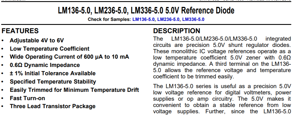
The LM336 comes in different voltages. Perhaps the part being used here is an LM336-5 which is a precision 5V Zener diode.

That would make the rest of your circuit agree.

Datasheet here: TI LM336-5 Datasheet

LM336-5

\$\endgroup\$
2
\$\begingroup\$

You missed a decimal point in your calculation. (12-2.5)/1K = 9.5mA , but it's actually (12-5)/1K = 7mA

It's a voltage follower and a 5V reference. The (unseen) op-amp power connections will be 0/12V.

The LM336 is old and has so-so performance, but is still available, and the LM759 is obsolete, but it's a power op-amp with unusual 325mA output current capability.

It's unclear why they would operate the LM336 at such a high current, given that it is specified at 1.0mA. The dynamic resistance is about 25% better but the 7:1 reduction in series resistance means that it will be 5x worse for line regulation. Self-heating drift will also be much worse.

A modern circuit would likely use different components, and use less power.

The circuit may be prone to oscillation with a substantial capacitive load on the 5V output, as the op-amp is not designed to drive a capacitive load. Oscillation would tend to destroy 5V devices attached to the output if you are trying to use it as a power supply.

You can get similar performance for pennies by using an LM7805 or 78M05 regulator and it is virtually impossible to coax it into oscillation.

\$\endgroup\$
1
\$\begingroup\$

There are both LM336-2.5 and LM336-5.0 reference diodes, so your circuit implies that the LM336 is the 5V variety. The op-amp is just a unity-gain buffer of the 5V reference voltage. It provides lower source impedance for the 5V signal. This can be a useful when the signal is being distributed to a few places in a circuit and is loaded down. If you change the 2.5V in your current calculation to 5V you will get the correct current.

\$\endgroup\$

Your Answer

By clicking “Post Your Answer”, you agree to our terms of service and acknowledge you have read our privacy policy.

Not the answer you're looking for? Browse other questions tagged or ask your own question.