I'm creating a circuit to do communications via a digital serial infrared link. My requirements are for the link to support relatively high speeds (maximum serial bit rate is 4,000,000 bps or 4Mbps) and for it not to draw a unreasonable amount of power; both requirements derive from the fact that I'm intending to drive this with a Raspberry Pi. The driver for this is a UART TX line directly from the Pi. I've chosen the Kingbright APTD3216F3C-P22 IR transmitter and a BC817-40 as the driver transistor (mostly because I have a lot of them leftover from an earlier project!). If it matters, this will be on FR4 PCB with 0402 resistors.
Calculations
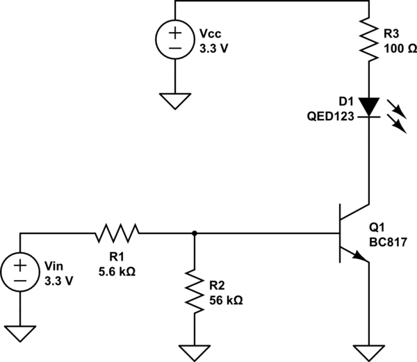
Here are my calculations for the various resistors. When the transistor is on, I want to drive 15mA of current through D1. Since the forward voltage drop across D1 is about 1.2V, and \$V_{CEsat} \le 0.7V\$, and the supply is 3.3V, I calculate the value of R3:
$$ R3 = \frac{(3.3 - 1.2 - 0.7)\text{V}}{15\text{mA}} = 93\Omega \approx 100\Omega$$
For R1, I am driving it with 3.3V and \$250 \le h_{FE} \le 600\$ for this transistor, so I calculate the resistor from the required base current times a factor of ten to make sure it's driven into saturation:
$$R1 = \frac{V_{in}}{10I_B} = \frac{3.3\text{V}}{150\text{mA}/250} = 5.5\text{k}\Omega \approx 5.6\Omega$$
To accommodate the higher speeds with clean transitions, I have R2 and used the rule of thumb that it should be about 10x R1. (Is there a better way to calculate that?)
When I do a SPICE DC sweep of Vin, however, the transition isn't very sharp, so I'm inclined to decrease R1 and increase R2, but I'm not sure what values to choose without just guessing.
Questions
- Are my calculations correct and reasonable?
- How should I increase the switching speed of the transistor?
- Is there a better design method? How should I choose the resistor values?
Schematic

simulate this circuit – Schematic created using CircuitLab

