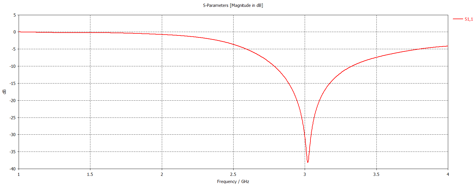
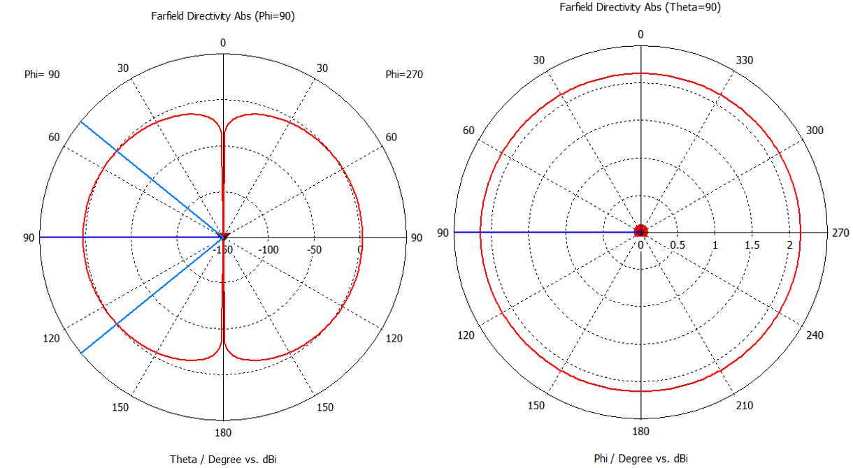
In order to make a comparison between an ordinary (3D) half - wavelength dipole and its printed (planar version), I've done a simulation in both cases. Both were designed to work at 3GHz (100mm wavelength). Input port is a voltage source with 75Ohm of impedance. To avoid dielectric effects, I've not considered any dielectric substrate for the printed dipole.
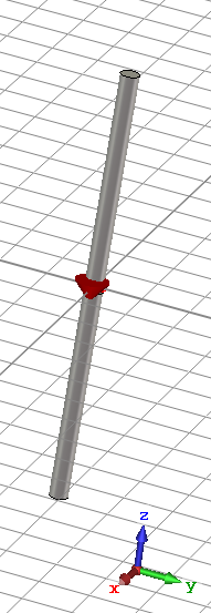
- The 3D dipole has been built with:
Length 45mm (a bit lower than half-wavelength. That's a choice the result of the simulator optimization).
Radius 1mm (much lower than the Length)
Gap1 1mm (much lower than the Length)
The results are:
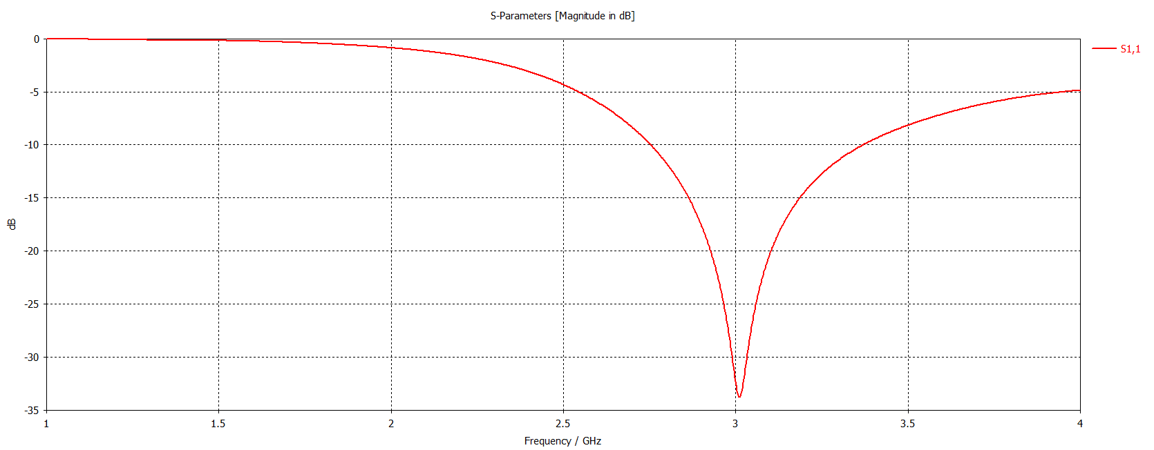
S11 (reflection coefficient). It's minimum at 3GHz. So it's fine.
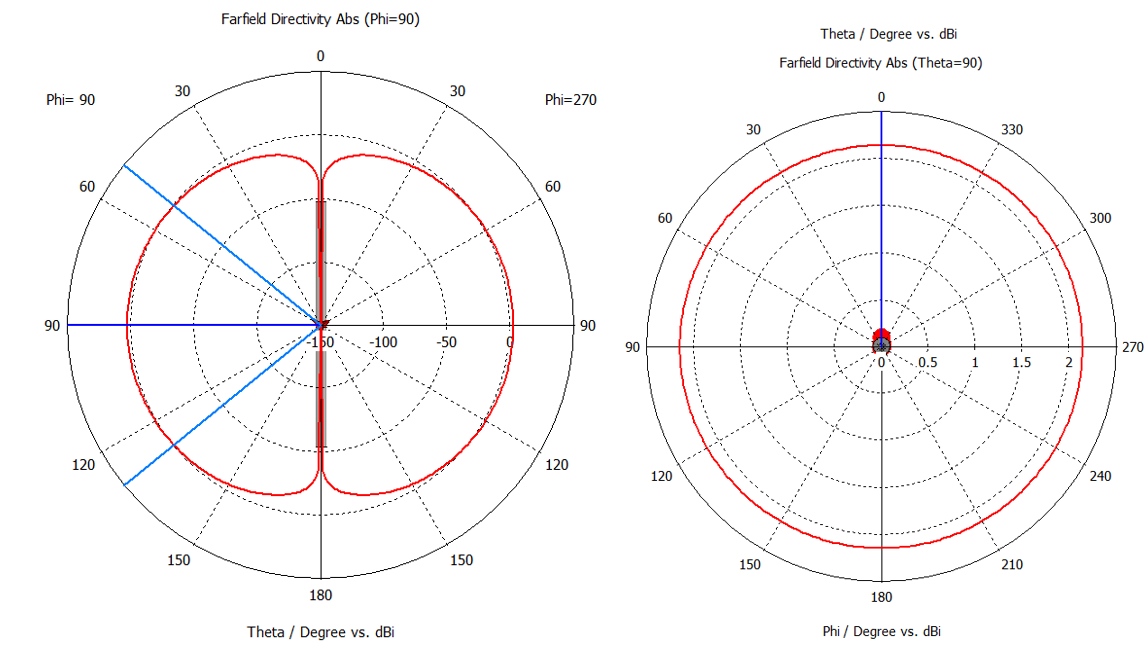
Radiation pattern cuts (at 3GHz)
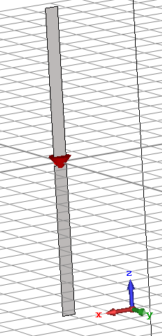
- The printed dipole has the same size values (Length 45mm, Width 1mm, Gap 1mm) of the 3D one, except for the fact it's a strip.
The results are:
S11 (reflection coefficient).
Radiation pattern cuts (at 3GHz).
In conclusion:
- same resonance frequency (for a fixed length)
- same matching at the resonance frequence
- same pattern shape and same directivity values
(Only very very very small differences are present in the previous graphs)
but a printed dipole has lots of advantages, being lightweight, easily embeddable with active devices in PCB, and flexible to make flexible pcb.
I can't believe there isn't at least one disadvantage in choosing the printed version. I would have expected a big variation in radiation pattern, since the 3d dipole has the same shape if seen from each direction on the transverse plane, while a printed dipole is a strip if observed frontally, and a wire if observed laterally. But the simulations say I'm wrong: the printed dipole is as omnidirectional (and with same directivity value) as the 3D dipole.

