1
\$\begingroup\$

I have this LED Driver - A80604

I need to generate 30V for my LED Driver String for generating 300mA.

In a previous question, I received an answer that I need to fix the current using the LED Driver to 300mA and the output voltage will take care of itself.

My question 1 - So, in that case, I want to understand whether this is a synchronous boost LED Driver circuit ? I am asking because what should I connect to the GATE and GDRV pins to?

My question 2 - What would be the voltage at the pins LED1-LED4 ? Would there be 0V after all the forward voltages of the LED or would there be some residual voltage after the forward voltages of the LEDs?

\$\endgroup\$
3
  • \$\begingroup\$ All of your questions are answered in the datasheet. You maybe don't need to read the fist 10 pages, but read 11-21 at least. \$\endgroup\$ Commented Mar 9, 2021 at 17:16
  • \$\begingroup\$ I tried, but was not clear on what to do. Could you please point \$\endgroup\$
    – user220456
    Commented Mar 9, 2021 at 17:26
  • \$\begingroup\$ Your first question is actually answered on the first page. "It implements a current-mode boost/SEPIC converter with gate driver for external N-MOSFET." And there is a typical application circuit there at the bottom of the page showing how to implement the boost feature. The second question is answered by applying the appropriate information from pages 11-21 to your specific use case. There are figures on 12 & 13 showing what you can expect to measure on the LEDn pins. \$\endgroup\$ Commented Mar 9, 2021 at 17:44

1 Answer 1

1
\$\begingroup\$

My question 1 - So, in that case, I want to understand whether this is a synchronous boot LED Driver circuit ?

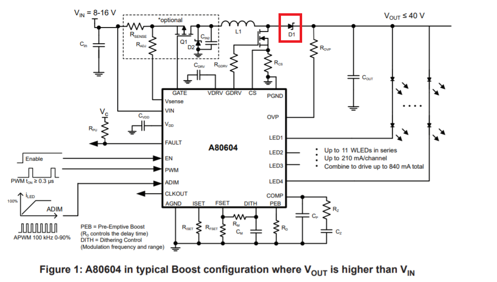
If you mean "boost" and not "boot" then no, it's not a synchronous boost circuit because it uses a standard diode here: -

enter image description here

I am asking because what should I connect to the GATE and GDRV pins to?

You connect GDRV as per the above circuit. The gate pin needn't be used if you don't need the optional circuit shown above.

My question 2 - What would be the voltage at the pins LED1-LED4 ?

It depends entirely on the dimming levels you have set on ADIM (pin 9) AND the natural forward volt drops of the strings of LEDs. Hard to be precise of course because this circuit controls current into the LED strings and, without a detailed LED spec it's guesswork.

\$\endgroup\$
4
  • \$\begingroup\$ Thank you for the answer. Could you tell me what does the optional circuit help us with? And my LED String has 10 LEDS with 3V each. So, 31V maximum with 300mA forward current for each LED. Now, could you tell me what would be the voltage at the pins LED1-4? \$\endgroup\$
    – user220456
    Commented Mar 9, 2021 at 17:41
  • \$\begingroup\$ @newbie I don't know what it does. I never read that bit. Do you want me to read it? It might be over-voltage or under voltage lock-out. Try searching those terms in the DS. \$\endgroup\$
    – Andy aka
    Commented Mar 9, 2021 at 17:43
  • 1
    \$\begingroup\$ Page 8 explains - it's OCP or over current protection - if the chip detects an over current situation the optional circuit can be used to remove power and protect the LEDs by the sound of it. Figure 37 and 38 also indicates where GATE is used when determining a fault condition. Figure 48 also gives more clues (OCP). \$\endgroup\$
    – Andy aka
    Commented Mar 9, 2021 at 17:58
  • 1
    \$\begingroup\$ Thank you very much for your answer. Let me just understand once and come to accept the answer. Thank you \$\endgroup\$
    – user220456
    Commented Mar 9, 2021 at 18:44

Your Answer

By clicking “Post Your Answer”, you agree to our terms of service and acknowledge you have read our privacy policy.