2
\$\begingroup\$

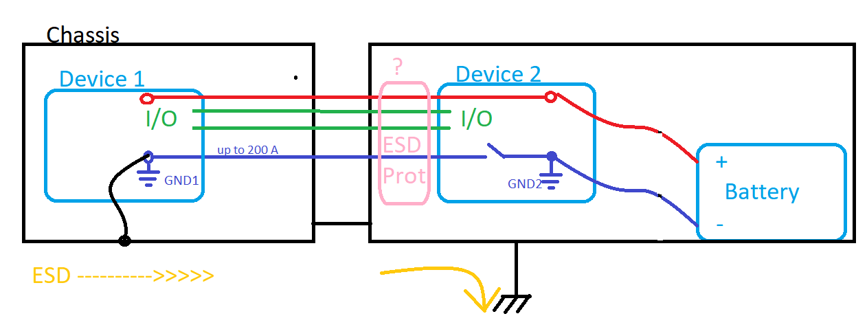
How to add ESD protection diodes to all cables (I/O, positive, ground)(see pink box below). Should I connect them to the chassis or battery negative terminal?

There may be some potential difference in ground and chassis due to large currents in ground cable (blue). enter image description here

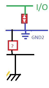
  • My initial guess is that I add ESD diodes between GND2 and IO/power lines
  • Do I need some protection device between chassis and GND2?

enter image description here

EDIT! It is observed that zapping the left side chassis with some 10kV causes the "Device2" to restart(fail). So there must be an arc between right side chassis and "Device2" somewhere because the ESD discharges through right side chassis.

\$\endgroup\$
2
  • \$\begingroup\$ Where is the ESD threat coming from? I mean you diagram looks like both circuits are in metal boxes that are earthed so is there really a problem? If you mean surge protection (not ESD) please do correct your question and explain where the threat is and what the potential victims are (data sheet links). \$\endgroup\$
    – Andy aka
    Commented Mar 10, 2021 at 17:18
  • \$\begingroup\$ Yes I mean ESD. The problem exists like described in my last EDIT. My theory is possible bad connection between the two enclosures. (the two enclosures are not ideal, mix of anodized[non conductive] aluminium and carbon fiber). The clearance between Device 2 and enclosure is sometimes very small << 1mm. ESD comes from left side chassis, but it is possible it could come from any signal cable in Device 1 too because the enlosure is not ideal. \$\endgroup\$
    – tarmogr
    Commented Mar 11, 2021 at 7:01

1 Answer 1

1
\$\begingroup\$

You want to connect TVSS devices directly at the point of protection and across the points you want to protect as close as possible. This means between the protected pin and the local ground. Don't think of TVSS like shielding, the earth reference doesn't do much for these transients and they are functioning as separate systems. If your chassis is grounded, this gives you a pretty good layer of protection if the wondering static charged fingers need to touch that first. But if the static charged fingers dodge the chassis and go straight for the GPIOs and power pins, then the TVSS can offer some protection to the local area that the fingers come in contact with independent of any earth grounding.

There is no need for TVSS diodes or other active components between digital grounds, analog grounds, and earth grounds. Sometimes it is desirable to connect them with a resistor to allow some level of isolation for noise without allowing any of them to float off to some arbitrary voltage with respect to each other. Earth ground should never be used as a current carrying path in your circuit design whereas the digital and analog grounds typically are the return path for the respective circuits. I typically use a 1 MegOhm or larger resistor between earth and other grounds.
\$\endgroup\$
2
  • \$\begingroup\$ I added addition camment to my question. In light of that can you provide any information if there is some diode needed between chassis and gnd2? \$\endgroup\$
    – tarmogr
    Commented Mar 10, 2021 at 15:16
  • \$\begingroup\$ It's supposed to go the chassis because you don't want the ESD flooding your plane. The chassis should have more free space capacitance anyways to absorb the charge. But it also means the chassis should be connected close the the point of entry. That's why ground is also connected to the chassis through a TVS. \$\endgroup\$
    – DKNguyen
    Commented Feb 4, 2022 at 16:12

Your Answer

By clicking “Post Your Answer”, you agree to our terms of service and acknowledge you have read our privacy policy.

Not the answer you're looking for? Browse other questions tagged or ask your own question.