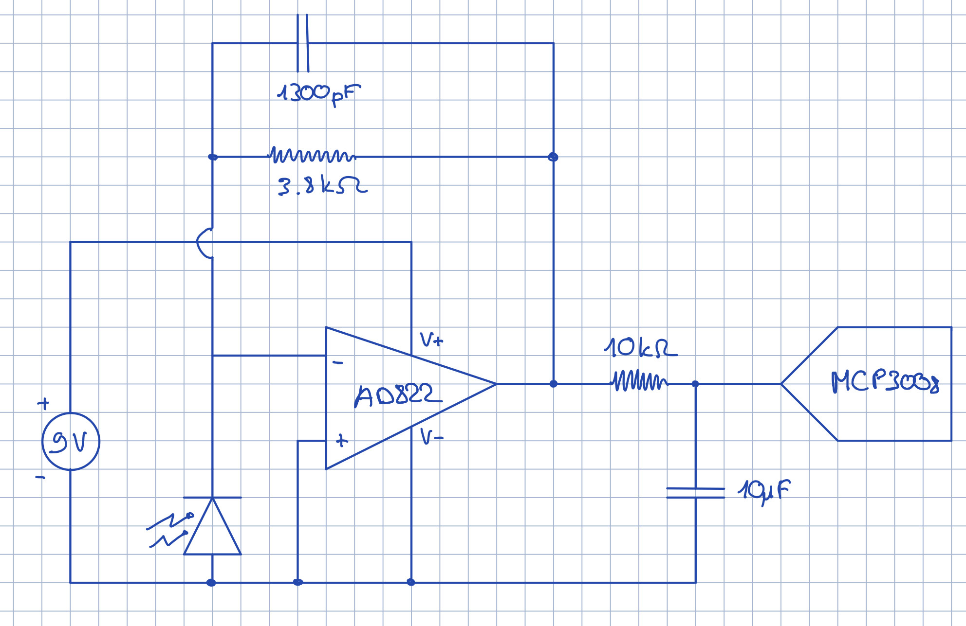
for my project, I am using a photodiode, that I connected to the AD822 OpAmp. This OpAmp should then be connected to the MCP3008 ADC. I am reading the data from the MCP3008 with a RaspberryPi. I am however getting weird readings from the ADC. I guess that this is because there is some sort of fluctuations in the voltage coming out of the OpAmp. Below there is a diagram of my wiring as it currently is (I am using the negative side of the 9V battery as ground):
I use single supply voltage for the OpAmp, as I do not have the possibility of dual supply.
If I try to measure the Voltage across the 10kOhm resistor with an multimeter, I get a value of 0V. However, according to my ADC the Voltage input Voltage fluctuates between 0 and 1.7V.
Now, if I disconnect the ADC and remove the 10µF capacitor and connect the 10kOhm resistor directly to ground, I get readings with my multimeter of 0.04V with ambient light and about 05.V if I put my flashlight over the Photodiode. So it seems to be working like that
Am I wiring something wrong? Are my capacitors or resistors wrong / at the wrong place?
Here are the datasheets: Datasheet Op Amp; Datasheet ADC
Thank you in advance!
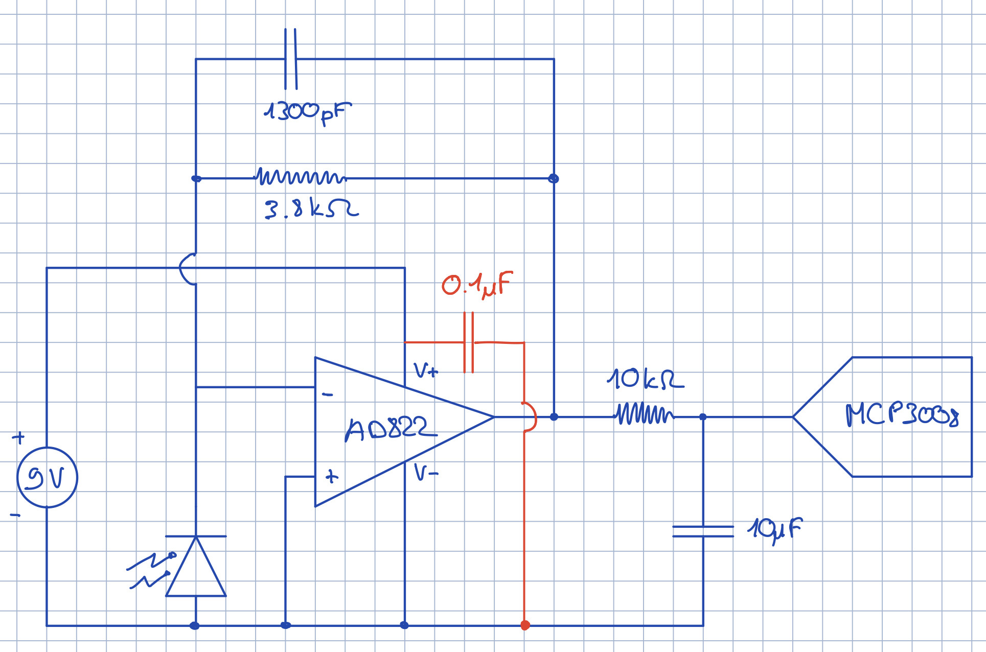
EDIT after jusaca response:
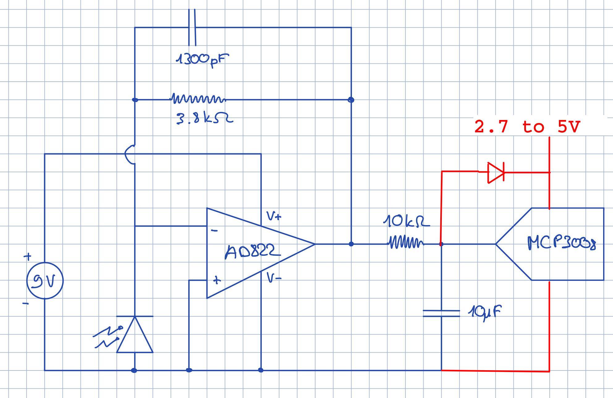
EDIT with Solution:
Jusaca, thank you for the decoupling advice and the relation between Rf and Cf.
I have worked on it more and finally realised what the last error was: I had to connect the negative side of the 9V battery to the ground of the MCP3008 and to the ground of the RaspberryPi. So connecting the entire "ground" side (the bottom line in my diagram) to both the negative side of the battery and the ground of the RaspberryPi and both grounds of the MCP3008! :)


