2
\$\begingroup\$

I am trying to understand how to connect an ESP32's UART pins to my raspberry pi 3B+'s I2C pins. I see several bridge chips available for this like TI's MSP430 Datasheet. But I am not very circuit savvy so I am having a difficult time. The pins I need to use on the ESP32 are: GPIO 9 and 10, RX and TX respectively (UART1). On the Raspberry Pi: GPIO 2 and 3, SDA and SCL respectively. Does anyone know answers to the questions below?

  1. Besides connecting the RPi, ESP, Vcc, GND pins to the bridge at the correct I/O positions on the chip, what additional circuitry would be needed to make good communication?

  2. What the ESP32 code would look like (Arduino IDE)?

  3. What the Pi's code would look like (python)?

\$\endgroup\$
7
  • 1
    \$\begingroup\$ Why do you want to use I2C on the Raspberry Pi? It does have an Uart as well, so why not connect them instead? \$\endgroup\$
    – PMF
    Commented Mar 12, 2021 at 18:15
  • \$\begingroup\$ Good question, the reason is UART pins are occupied by another module. \$\endgroup\$
    – Feynman137
    Commented Mar 12, 2021 at 18:16
  • 1
    \$\begingroup\$ The ESP32 has an I2C interface, the PI has an I2C interface, why not use that? \$\endgroup\$
    – Lior Bilia
    Commented Mar 12, 2021 at 18:43
  • \$\begingroup\$ I was just wondering about this... Both modules I2C interfaces are unoccupied in my application. I have never tried this before. \$\endgroup\$
    – Feynman137
    Commented Mar 12, 2021 at 18:49
  • 1
    \$\begingroup\$ @Feynman137: Get yourself a Pi4. It has 6 Uarts ;-) \$\endgroup\$
    – PMF
    Commented Mar 12, 2021 at 18:53

2 Answers 2

1
\$\begingroup\$

schematic

simulate this circuit – Schematic created using CircuitLab

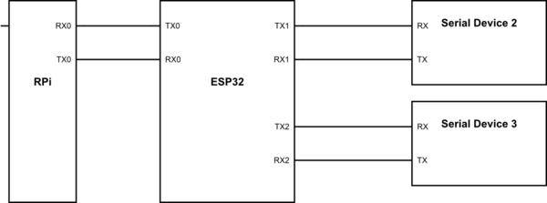
The ESP32 has more than 1 UART. Although it is common to only use one of them in the default configuration, the ESP32 has 3 UARTs. You can configure which GPIO pins to use by using the uart_set_pin() function. You should check the datasheet or the Espressif website for the details.

Using multiple UARTs allows the ESP to act as a Serial Bridge. This function is frequently implemented with the different flavors of ESPs as a WiFi Serial Bridge, but it works for wired connections as well.

UART Page

\$\endgroup\$
1
  • \$\begingroup\$ ESP does have multiple UART, but Pi 3b+ doesn't have pins for more than one UART and these pins are currently occupied. This is the issue. I was not aware of the uart_set_pin() function though, so I appreciate the suggestion. \$\endgroup\$
    – Feynman137
    Commented Mar 15, 2021 at 4:11
1
\$\begingroup\$

A others have commented, the easiest way to communicate between the ESP32 and RPi is using asynchronous serial; if you don't have a spare serial port on the Pi, you can add a USB-to-serial adaptor.

If you choose one with an FTDI chip, then just plug it in to the Pi and you get another serial port; the other common type of adaptor uses the CP2102 chip, and I think this might require you to install a driver on the Pi, but you'll find plenty of instructions how to do this on the Web, e.g. this page

Make sure that you are using an adaptor with the correct voltage level (3.3V logic signals, not 5V or RS232 voltages), then connect the ground wires together, and Tx on Pi to Rx on ESP32, Rx on Pi to Tx on ESP32.

With regard to how you use this link to communicate, any character you send on one side will just appear at the other. However, it is prudent to create a simple communication format, such as a command letter, maybe some numeric values, then a Carriage Return to signal the end of the command line. This has 2 benefits; it means you can use a serial terminal to enter commands manually, and also it avoids the possible confusion where the recipient tries to take action when it has only received part of a command.

\$\endgroup\$

Your Answer

By clicking “Post Your Answer”, you agree to our terms of service and acknowledge you have read our privacy policy.

Not the answer you're looking for? Browse other questions tagged or ask your own question.