0
\$\begingroup\$

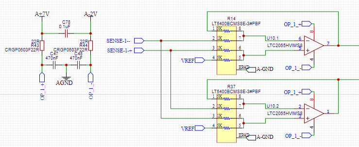
I'm trying to create a "precision" fully differential amplification stage, to measure uA on a 10R shunt, and mA on a 0.01R shunt. shunt resistance values are set at those values for burden voltage reasons. thus the voltage would be ~10uV/uA and ~10uV/mA.

my topology of my frontend is two sets of Shunt -> x10 differential amp -> PGA -> Muxed input of 24 bit ADC (LTC2442).

my question here pertains to the x10 stage amplifier. I've come up with the circuit shown, but it does have its downfalls, mainly requiring 2x 8$ resistor packages each. Cost is not the issue, I just feel that I might be overlooking a simpler solution. I might add a potentiometer to adjust the CMRR, but I'm hoping the resistors match closely enough.

My question is whether or not my design is a good implementation, any improvements to my design, or a solution requiring less matched precision resistor packages.

Pictured is a "clear" picture of what I'm considering using (NOT the one used). the one actually used has two packages of 4x 5K and 4x 1K resistors, as the 4 values need to match closely, but the ratio is software calibrated. VREF = 2.5v. SENSE flags are connected directly to shunts.

enter image description here

\$\endgroup\$
5
  • \$\begingroup\$ Why have you got two independent channels of measurement being fed the same signal? \$\endgroup\$
    – Andy aka
    Commented Mar 17, 2021 at 15:50
  • \$\begingroup\$ I'm doing a project right now, where I need to measure 1uA-10mA, and I'm using 10R for mA and 1k shunt for uA, with dedicated 50V/V amp fed into 12-bit ADC - thanks to larger voltage drops I don't need crazy resolution ADC. The whole construction costs me a pair of bucks. There are 200V/V amps and even 500V/V amps like INA180 or other INA series - they have integrated resistors, take a look. Are you sure you need those tiny shunts and there is no other way? I compensate burden voltage in software. \$\endgroup\$
    – Ilya
    Commented Mar 17, 2021 at 15:50
  • \$\begingroup\$ they are not fed same signal, channel one is 10R (uA), channel 2 is 0.01R (mA). Yes I do for in circuit current measuring, where the onboard regulator voltage cannot be changed. i.e. developing battery powered device, want to know current used by a device on the pcb. yes i could use an external supply to compensate, but that's not the point. 1.2v rail can take quite a hit when burden voltage is involved. \$\endgroup\$
    – super7800
    Commented Mar 17, 2021 at 16:00
  • \$\begingroup\$ Oh yes they are - I can read schematics. \$\endgroup\$
    – Andy aka
    Commented Mar 17, 2021 at 16:21
  • \$\begingroup\$ my apologies if it wasn't clear, here is a full picture of the two channels. its a fully differential amplifier, differential in, differential out. i.postimg.cc/d3c7CX1v/full.png \$\endgroup\$
    – super7800
    Commented Mar 17, 2021 at 16:24

2 Answers 2

1
\$\begingroup\$

I do for in circuit current measuring, where the onboard regulator voltage cannot be changed. i.e. developing battery powered device, want to know current used by a device on the pcb

Solution 0: ucurrent

Solution 1: Power the device whose current you want to measure with a separate micropower LDO, and put the current sense resistor in the input of the LDO so you don't care about burden voltage. This adds the current consumption of the LDO to the measurement, though.

Solution 2: build your own regulator

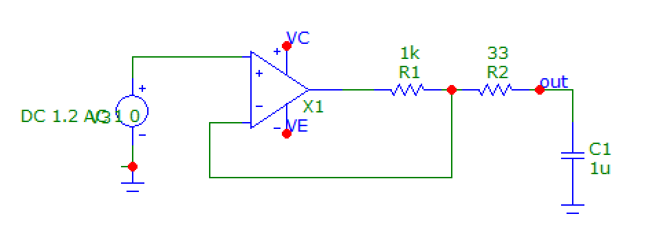
enter image description here

The output current can be measured on R1, which can be a higher value resistor since the opamp compensates for the burden voltage.

Solution 3: ditch the instrumentation amp.

The interesting and expensive feature of the instrumentation amp is common mode rejection no matter what the common mode voltage is, from a high impedance source. However, your source impedance is low, and your common mode voltage is known and it is constant. So you don't need to pay for features you don't need, and you can use this much simpler circuit instead:

enter image description here

Voltage on R1 is voltage on shunt multiplied by gain of opamp (1+R3/R2).

The opamp should be low offset, and the input current is part of the measurement, so I'd suggest a FET input chopper opamp.

Then... with all these solutions you still need a differential amp, but since the differential voltage is now quite large, required common mode rejection is much less, so you can use the diff amp in your ADC.

\$\endgroup\$
2
  • \$\begingroup\$ thanks. option 0,1,&2 would be a non-option in my case, perhaps i should have specified that. i'm building a "handheld" device with a color display to do datalogging, graphing, and other analysis of the signal. if I just wanted to measure currents on my bench, id just use the ucurrent as you suggested and a 6.5 digit bench meter. I will look into the accuracy of the third solution that you provided thanks. \$\endgroup\$
    – super7800
    Commented Mar 20, 2021 at 20:40
  • \$\begingroup\$ OK, if it's a handheld device, then there is no common mode... In a multimeter, the "COM" terminal is just the internal multimeter ground, so when it measures current, its internal shunt has 0V common mode... \$\endgroup\$
    – bobflux
    Commented Mar 20, 2021 at 21:23
1
\$\begingroup\$

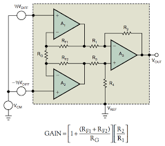
To measure this kind of signal, what you need is an instrumentation op-amp, which is basically a circuit comprising several op-amps in a single package.

enter image description here

Understanding CMR and instrumentation amplifiers

Those instrumentation op-amps allow high impedance input, are very precise and can measure very small voltages.

Those can work down to nV level of differential input.

\$\endgroup\$

Your Answer

By clicking “Post Your Answer”, you agree to our terms of service and acknowledge you have read our privacy policy.

Not the answer you're looking for? Browse other questions tagged or ask your own question.