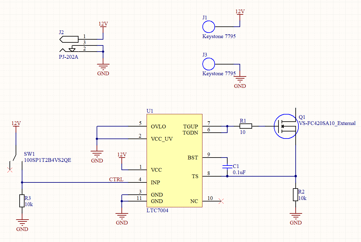
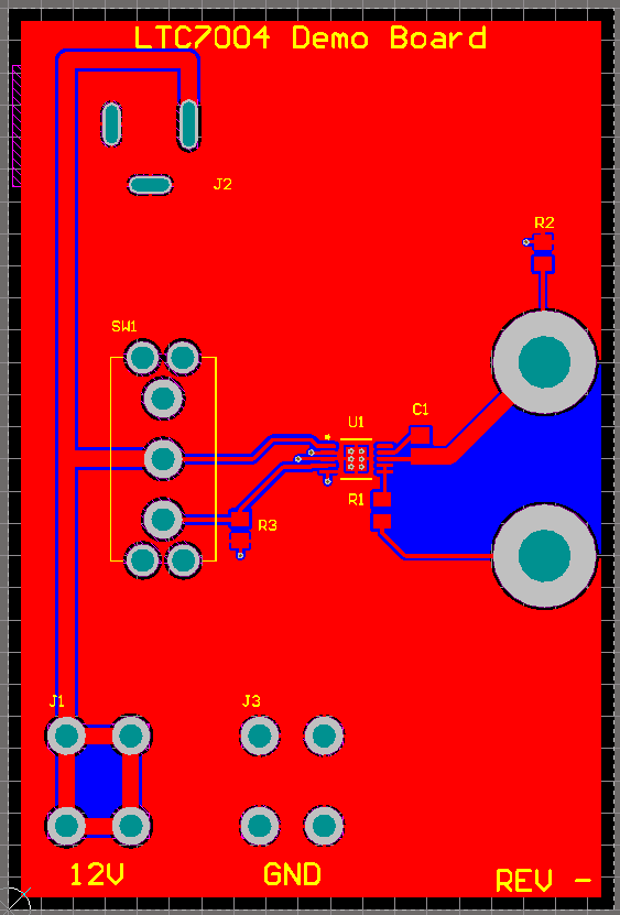
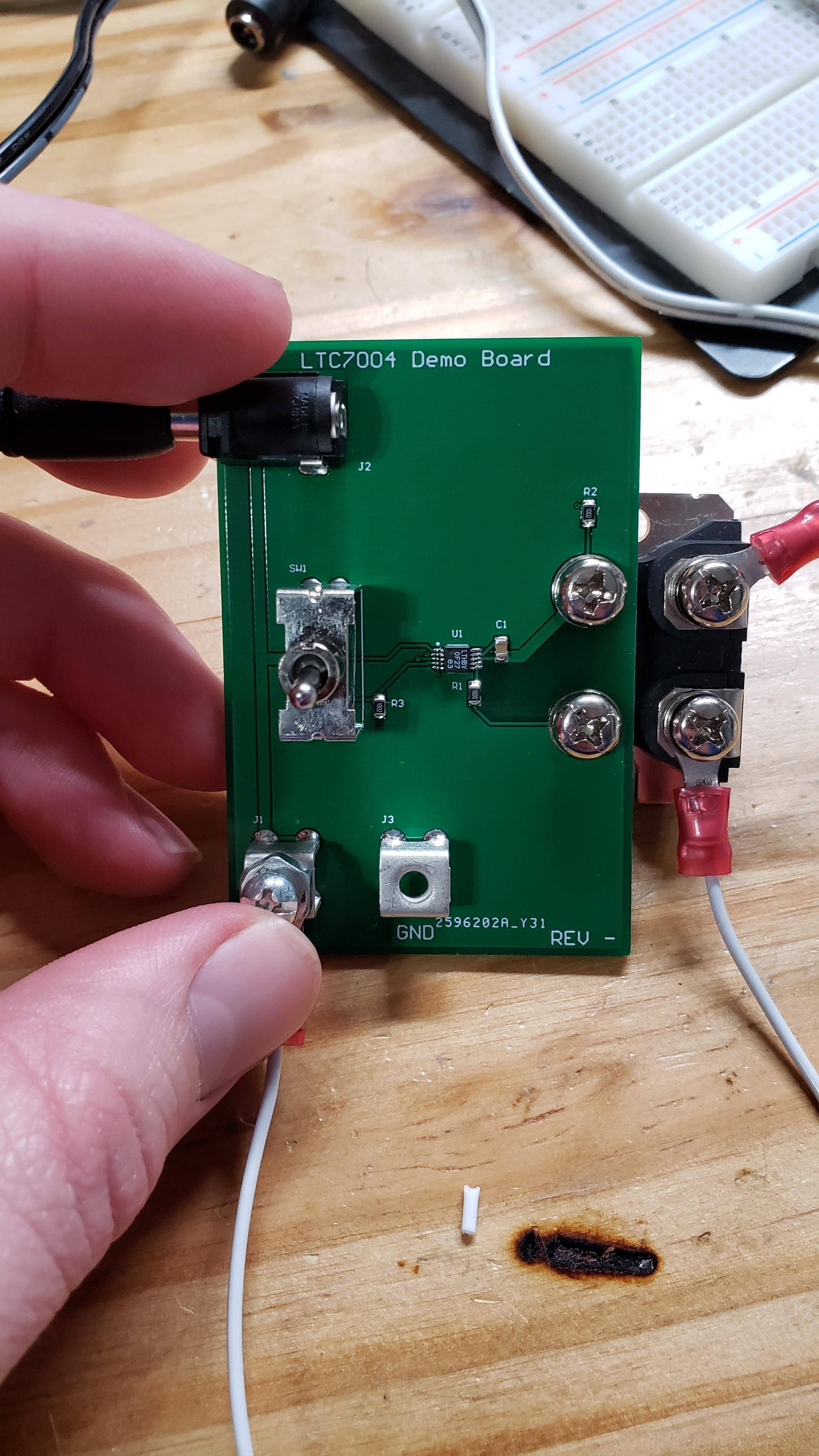
I designed a small breakout board for the LTC7004 gate driver to test some high-power MOSFETs. While initially powering the circuit using a 12V AC adapter, everything worked fine and the gate drive pins (TGUP/TGDN) would output 24V when the switch was on. I then moved the setup to run off of a 12V car battery and attached a 1/2 ohm dummy load in parallel with R2. At this point the LTC7004 stopped working and will no longer work even using the bench power supply. What might I have done wrong? There is no visible damaged to the chip or PCB and nothing got hot.
-
\$\begingroup\$ No decoupling caps, for one. You should always put decoupling caps in parallel with EVERY power-GND pin pair for EVERY IC unless you know specifically why you don't need to. There should also be a bulk decoupling capacitance. \$\endgroup\$– DKNguyenCommented Mar 17, 2021 at 23:09
-
1\$\begingroup\$ @DKNguyen, yeah, I already realized that mistake but that shouldn't break the chip either. \$\endgroup\$– user8908459Commented Mar 17, 2021 at 23:11
-
\$\begingroup\$ Do you actually still measure a voltage on the charge pump across the cap? \$\endgroup\$– DKNguyenCommented Mar 17, 2021 at 23:24
-
\$\begingroup\$ @DKNguyen, there is no longer a voltage on the charge pump \$\endgroup\$– user8908459Commented Mar 17, 2021 at 23:26
-
\$\begingroup\$ @DKNguyen, based on page 2 of this document, I am wondering if hot-plugging got me in trouble. analog.com/media/en/dsp-documentation/evaluation-kit-manuals/… \$\endgroup\$– user8908459Commented Mar 17, 2021 at 23:26
2 Answers
No decoupling caps, for one. You should always put decoupling caps in parallel with EVERY power-GND pin pair for EVERY IC unless you know specifically why you don't need to. There should also be a bulk decoupling capacitance.
Your problem is probably that high-side gate drivers runing off bootstrap capacitors can't work at continuous duty. They rely on the output node periodically going LO to allow a current path through the bootstrap diode then bootstrap capacitor to GND into order to refresh it. In a half-bridge this occurs whenever the low-side transistor turns on which happens in normal operation while commutating a motor or inverter.
In your case, you have it flowing through a 10K resistor which does a whole bunch of bad things. While it does provide a current path to recharge the bootstrap while the transistor is off, the current is severely limited, and while on, the boostrap current is drained.
WHen you put in a 1/2 Ohm dummy load, the charge current was probably too high and destroyed the internal bootstrap diode causing it to fail short.
-
1\$\begingroup\$ This chip has an internal charge pump and is designed to operate at continuous duty. See the datasheet. Page 1 list "static switch driver" under the list of applications. Page 7 shows the internal charge pump. \$\endgroup\$ Commented Mar 17, 2021 at 23:19
-
\$\begingroup\$ @user8908459 Oh, I see. Hold on. Lemme read the datasheet \$\endgroup\$– DKNguyenCommented Mar 17, 2021 at 23:20
-
\$\begingroup\$ I believe I found the issue. Soldered on a new chip and paid careful attention to when it broke. Everything worked fine until I attached the large dummy loads. When I switched the MOSFET on, it worked as expected. However, after I switched it off and then back on again, nothing worked. I think the large inductive load is discharging through the TS pin. See page 12 in the datasheet. \$\endgroup\$ Commented Mar 18, 2021 at 1:20
-
4\$\begingroup\$ @user8908459 Nowhere did you indicate an inductive load in your original post. You only indicated 10K resistors and 1/2 Ohm resistive loads. \$\endgroup\$– DKNguyenCommented Mar 18, 2021 at 3:24
What might I have done wrong?
Exceeded the voltage on INP, Vcc or some other pin. If you don't have good ESD procedures (wearing a wrist strap and have an ESD bench) its very possible that you could have zapped the part. (most of the pins can tolerate up to 15V, ESD can reach thousands of volts)
Another thing to check is if the mosfet is burned out, sometimes they fail and short the source to gate. The driver outputs TGUP TGDN can tolerate lots of voltage, but little or no current if the mosfet failed its possible that the gate driver is also dead:
Do not apply a voltage or current source to these pins. They must be connected to capacitive loads only; otherwise permanent damage may occur.
Source: Note 6 of the LT7004 datasheet


