0
\$\begingroup\$

I am currently studying the thevenin circuit, but I don't know how to calculate it due to the complex sources with dependent source. I've been calculating for more than 2 hours and I can't do it, so I ask for help. Thank you in advance! enter image description here
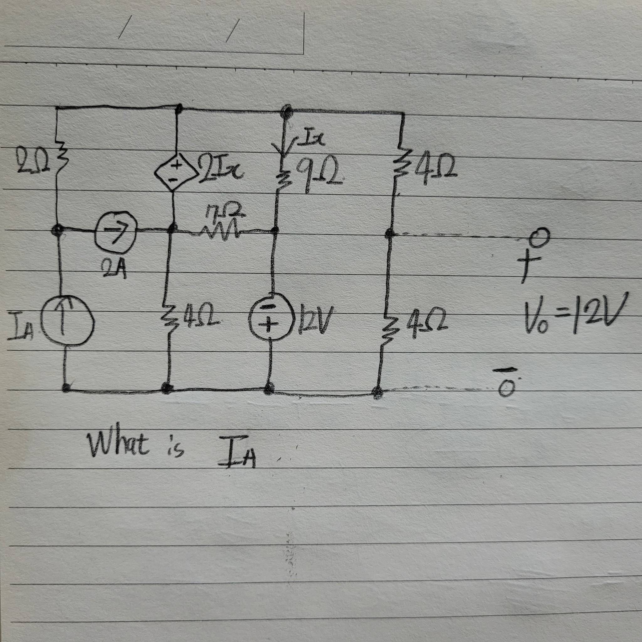
Picture's circuit, what is current I_A?

\$\endgroup\$
4
  • \$\begingroup\$ Why upside down? Did you want to learn matrix nodal analysis? Or just use equivalent branches converted? Or just solve KCL KVL? \$\endgroup\$
    – D.A.S.
    Commented Mar 22, 2021 at 17:40
  • \$\begingroup\$ Actually I don't know much about circuit theory. I only know how to use KCL and KVL, but can I solve the problem using only two methods? \$\endgroup\$
    – 김현우
    Commented Mar 22, 2021 at 17:48
  • 1
    \$\begingroup\$ You will probably need Ohm's Law as well. We don't hand out homework solutions so show us all of your work. Then ask a specific question if you get stuck. \$\endgroup\$ Commented Mar 22, 2021 at 18:18
  • \$\begingroup\$ If you knew KVL and KCL you could have solved it or at least upvote @jonk ‘s great effort to help you \$\endgroup\$
    – D.A.S.
    Commented Mar 22, 2021 at 21:28

2 Answers 2

0
\$\begingroup\$

You (not this actor?) should just follow these steps:

  1. Label the bottom node (wire) that is attached to your (-) terminal as the ground reference (\$0\:\text{V}\$. As you work around the schematic and label other nodes (wires) with voltage values, these values will all be labeled so as to reference their values with this node. (All voltage values are differences between two points.)
  2. You can now just assign \$V_O\$ and its value to the node (wire) shared by both \$4\:\Omega\$ resistors at the right side of the schematic. (It's not much of a change, but I'm trying to drill in the value of labeling the ground node in step 1. We are labeling nodes with respect to our new ground reference.)
  3. Label the node (wire) that is shared by the \$7\:\Omega\$ and \$9\:\Omega\$ resistors with the known voltage implied by your \$12\:\text{V}\$ voltage source. You have enough information to do that. Make sure that you label this node with respect to the ground node. This value is the difference between this node and ground (from step 1.) Call this voltage \$V_1\$ and annotate your schematic with its name and value, too.
  4. Compute the current implied by the measurement of \$V_O\$ across the \$4\:\Omega\$ resistor at the lower right of your schematic. You know what this current must be already from the information available. Call this current \$I_1\$ and annotate your schematic to include an arrow showing the direction of the conventional current as well as its magnitude.
  5. Using KCL, you know that the current in the \$4\:\Omega\$ resistor in the upper right of your schematic must have the same magnitude as \$I_1\$. You also know the direction of conventional current, from KCL. So annotate the schematic with this current arrow and label it \$I_1\$, as well.
  6. \$I_1\$'s magnitude and direction now also implies a known voltage and polarity across the \$4\:\Omega\$ resistor in the upper right of your schematic. Compute this voltage and add it to \$V_O\$ in order to get the value of the top node (wire) of your schematic. Call this voltage \$V_2\$ and annotate the schematic with the name and its value.
  7. You can now compute \$I_X=\frac{V_2-V_1}{9\:\Omega}\$, as you know the voltages on either end of the \$9\:\Omega\$ resistor. You also know its direction. So annotate the schematic with this newly computed value. (You already have a label for it.)
  8. You can now work out the voltage difference across the dependent voltage source, as \$2\,I_X\$, and thus compute the node voltage, let's call it \$V_3\$ (with reference to ground from step 1, of course), where the \$7\:\Omega\$ resistor and \$4\:\Omega\$ resistor connect up with the dependent voltage source (and a current source.) You already have \$V_2\$ from step 6 and a voltage difference from there to \$V_3\$, so you must be able to compute \$V_3=V_2-2\cdot I_X\$.
  9. Now you can compute the currents in both the \$7\:\Omega\$ resistor (call it \$I_2\$) and \$4\:\Omega\$ resistor (call it \$I_3\$) mentioned in step 9. \$I_2=\frac{V_3-V_1}{7\:\Omega}\$ and \$I_3=\frac{V_3-0\:\text{V}}{4\:\Omega}\$. Annotate the schematic with these values and conventional directions.
  10. Using KCL, analyze node \$V_3\$. You know three of the four currents, now, so you can compute the fourth one -- the current present in the dependent voltage source. Call this current \$I_4\$ and annotate the schematic with its value and direction.
  11. Using KCL, analyze node \$V_2\$. You know three of the four currents, now, so you can compute the fourth one -- the current present in the \$2\:\Omega\$ resistor and its direction. Call this current \$I_5\$ and annotate the schematic with its value and direction through the \$2\:\Omega\$ resistor.
  12. Using KCL you can now work out the current value in \$I_A\$.
\$\endgroup\$
4
  • \$\begingroup\$ Maybe Hyunwoo Kim should change studies to communication. \$\endgroup\$
    – D.A.S.
    Commented Mar 22, 2021 at 21:27
  • \$\begingroup\$ @TonyStewart Maybe so. ;) \$\endgroup\$
    – jonk
    Commented Mar 23, 2021 at 0:40
  • \$\begingroup\$ In korea kim hyunwoo is everywhere lol(it's one of the most common name) Thank you for your detail explain. \$\endgroup\$
    – 김현우
    Commented Mar 23, 2021 at 3:10
  • \$\begingroup\$ @김현우 No problem. I hope the steps helped. Thanks for the short note about Korean names. I really appreciate the fact that we all get to chat and learn from each other in the web, today. It's a real treat! (I also have an avid follower who likes to down-vote me out of entirely personal and emotional reasons -- no logic whatsoever. It happens and it's their problem. Happens in all societies.) \$\endgroup\$
    – jonk
    Commented Mar 23, 2021 at 3:14
1
\$\begingroup\$

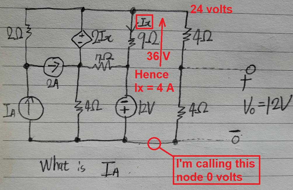
Just start putting numbers onto your diagram and, because this is homework, I'm not going to feed you the final answer but a halfway answer: -

enter image description here

So, I've given you Ix, can you run with this now? Next step, calculate the voltage across the 7 Ω resistor.

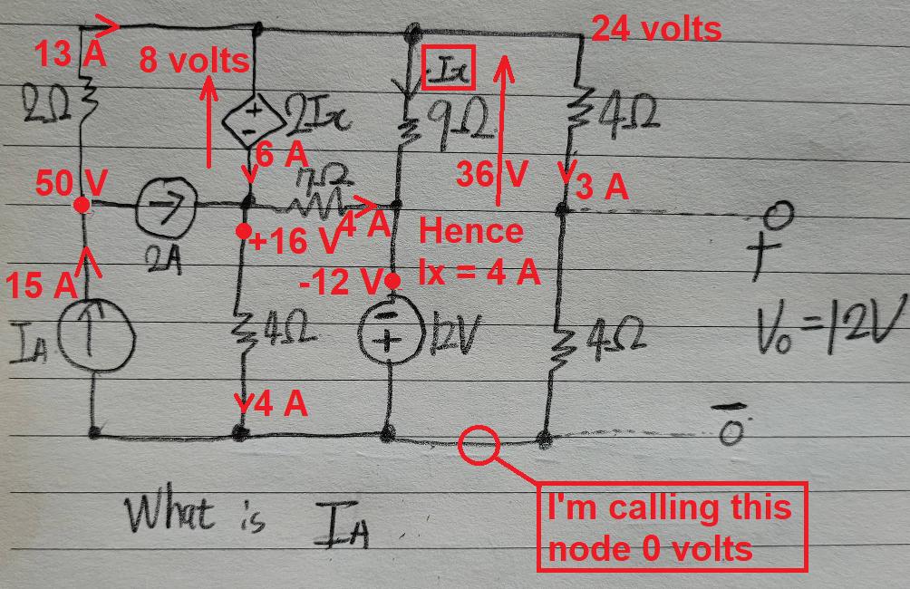
@김현우 did you get your answer as 15 amps?

yes i calculated I_A is 15A :) Thanks! – 김현우

enter image description here

\$\endgroup\$
5
  • \$\begingroup\$ You may need to identify your reference node as ground. I know it's kind of implied and obvious to you and me. But sometimes it helps to explain what you mentally did. :) \$\endgroup\$
    – jonk
    Commented Mar 22, 2021 at 17:51
  • 1
    \$\begingroup\$ @jonk thank you for reminding me and fixed! \$\endgroup\$
    – Andy aka
    Commented Mar 22, 2021 at 17:53
  • \$\begingroup\$ Thank you Andy aka. it's very helpful answer for me. i missunderstand that it must solve to Thevenin theorem. \$\endgroup\$
    – 김현우
    Commented Mar 23, 2021 at 3:13
  • \$\begingroup\$ @김현우 did you get your answer as 15 amps? \$\endgroup\$
    – Andy aka
    Commented Mar 23, 2021 at 9:08
  • \$\begingroup\$ yes i calculated I_A is 15A :) Thanks! \$\endgroup\$
    – 김현우
    Commented Mar 23, 2021 at 9:21

Your Answer

By clicking “Post Your Answer”, you agree to our terms of service and acknowledge you have read our privacy policy.

Not the answer you're looking for? Browse other questions tagged or ask your own question.