1
\$\begingroup\$

I'm working on a project that will have an Arduino Nano 33 IoT controlling a MG996R Servo. The goal is to get the batteries to last as long as possible, as it will always be on, and will only rotate the servo 2-4 times per day. The Servo's signal pin can be controlled by the Arduino, but if the Servo's power pin is connected directly to power it will constantly draw power even when the it is not being used, so I want to use a transistor to cut off its connection to power and save the batteries. I also want the transistor to take as little power as possible between the collector and emitter pins so the servo can be at as close to full power as possible (I don't care about the base pin as long as it can be controlled by a 3.3 V PWM pin on the Arduino Nano).

How do I decide between BJT or FET transistors? And within those categories how do I determine which will be best for my project? If you can tell me which one, GREAT! But I'm really looking for resources so that in future projects I know the difference and can pick which transistor will be most efficient for my projects. My Diagram This isn't exactly how my project will look, but it is close and the best visual representation I could figure out how to make. My project will have 5 V input and an Arduino Nano instead of the Uno.
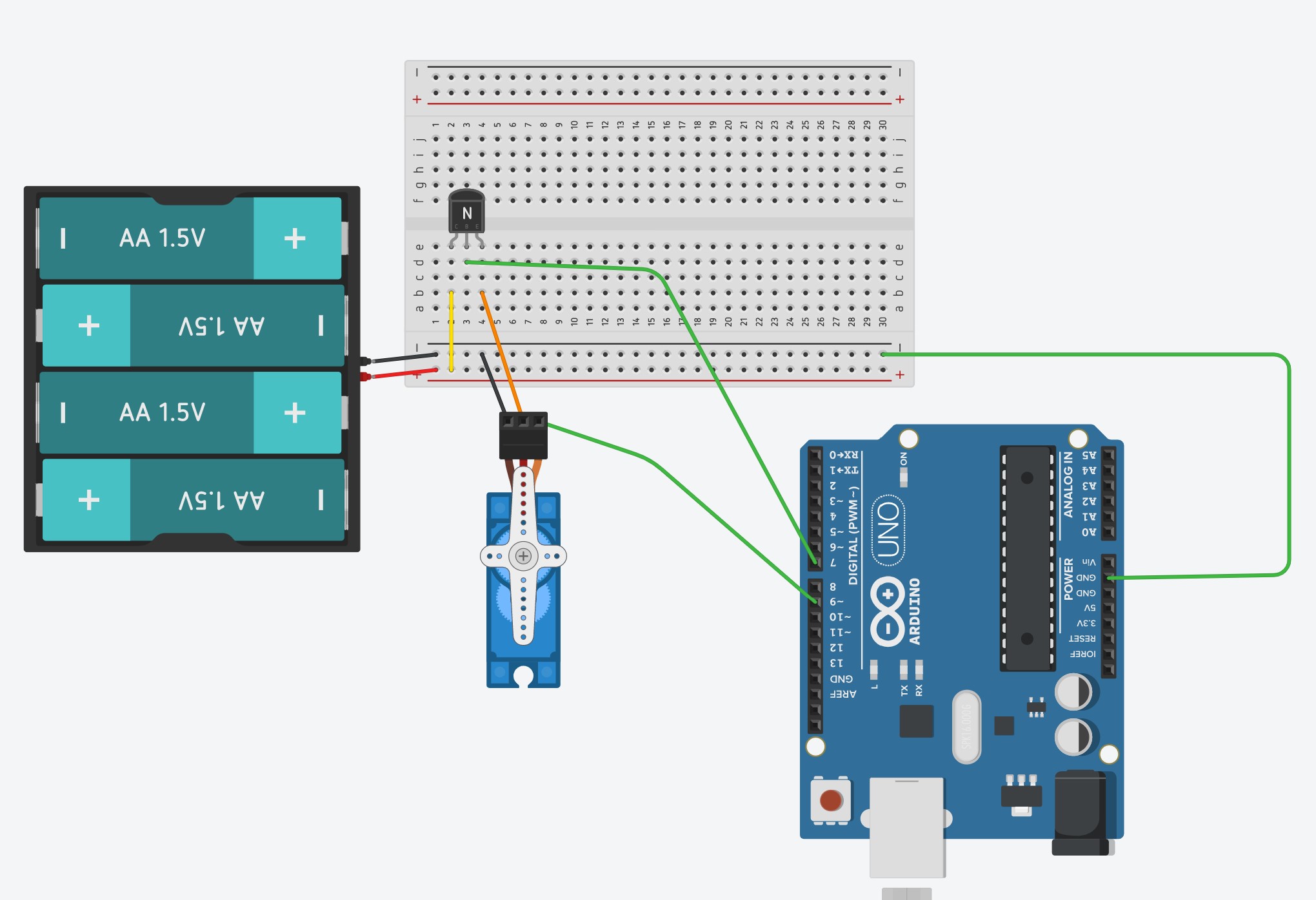
\$\endgroup\$
8
  • \$\begingroup\$ Is the Nano doing anything else in between servo changes? Or just sitting there? \$\endgroup\$
    – jonk
    Commented Mar 25, 2021 at 19:57
  • \$\begingroup\$ Currently just sitting there, but in the future additional features may be added \$\endgroup\$ Commented Mar 25, 2021 at 19:58
  • \$\begingroup\$ 1) the type of transistor doesn't really matter, how you use it matters a lot more. 2) include a schematic (there is a tool to draw one), what you have is a wiring diagram and that's not the same. 3) if the servo consumes current when "doing nothing" consider using a better servo. 4) there can be issues when disconnecting the supply from ICs and a servo might contain an IC, if there's an input pin with a voltage then that voltage might still power the IC or servo. 5) go look up some examples how to make an Arduino consume little power because it can be done but is not trivial. \$\endgroup\$ Commented Mar 25, 2021 at 20:00
  • \$\begingroup\$ P-channel MOSFET is what you want. You want to do a high side switch. I will try to write up an answer later (or link to one). But just to get you pointed in the right direction to start. \$\endgroup\$
    – user57037
    Commented Mar 25, 2021 at 20:02
  • 2
    \$\begingroup\$ No, a BJT will not reduce the voltage to the servo by 0.7V. The 0.7V is the Vbe voltage. The servo voltage will be reduced by the saturation voltage of the transistor, which is typically significantly less than 07V. \$\endgroup\$ Commented Mar 25, 2021 at 21:10

1 Answer 1

1
\$\begingroup\$

Silly to entertain using a BJT for this. You want to use a P-channel MOSFET. You can turn it on with another (small) N-channel mosfet such as a BSS138. See below.

It is true that the control signal to the servo may need to be low at all times when the PMOS is switched off. I haven't played with servos enough to be sure about that. You may need to write your code so that after you turn on the PMOS, wait 50ms or something before you start controlling the servo. And stop controlling the servo before you turn off the PMOS. By "stop controlling the servo" I mean force the control signal to be low continuously.

schematic

simulate this circuit – Schematic created using CircuitLab

\$\endgroup\$
3
  • \$\begingroup\$ Why use the P-channel and N-channel, instead of a single n-channel mosfet? \$\endgroup\$ Commented Mar 26, 2021 at 19:54
  • 2
    \$\begingroup\$ You can't use N-channel on the high side unless you can drive the gate 5V (or whatever) higher than the voltage you are trying to switch. Sometimes you can use NMOS on the low side. But in this case if you put NMOS on the low side, then there will be problems with the control signal that goes to the servo. The servo GND is at VBAT when the low side NMOS is off. That means that the control input to the servo will be at -VBAT (which is GND on the arduino side). That will fry the servo. \$\endgroup\$
    – user57037
    Commented Mar 26, 2021 at 21:32
  • \$\begingroup\$ It is safer/better/easier if there is only one GND and they are all connected together. \$\endgroup\$
    – user57037
    Commented Mar 26, 2021 at 21:33

Your Answer

By clicking “Post Your Answer”, you agree to our terms of service and acknowledge you have read our privacy policy.

Not the answer you're looking for? Browse other questions tagged or ask your own question.