3
\$\begingroup\$

I am writing a program to control a dot matrix LCD and display some text on it via PC serial port interface. The LCD have a Pin to Input Clock Signals. I have searched a lot on internet about clock input signals but I sill cant fully understand it. Yet what I got is that the clock signal is a continuous chain of ONs and OFFs right after each other, should be send to the device in parallel with data. When its state changes it pushes data to device. The time period of each ON or OFF pulse should be same as the data pulse.

Clock Signal: 10101010
Data Signal : 11010011

Now if I am right, why don't we simply use an appropriate oscillator with device to produce clock signals? And if I am wrong please guide me to the right direction.

\$\endgroup\$
5
  • \$\begingroup\$ Can you give us the LCD model number? \$\endgroup\$
    – Oli Glaser
    Commented Jan 20, 2013 at 16:30
  • \$\begingroup\$ The LCD is of Nokia 3310 mobile phone based on a PCD8544 controller. \$\endgroup\$ Commented Jan 20, 2013 at 16:34
  • \$\begingroup\$ @OliGlaser It isn't really needed, this is just a standard question about why using a clock line. It's useful for clock lines on any communicating device: why not use an oscillator instead. \$\endgroup\$
    – user17592
    Commented Jan 20, 2013 at 16:35
  • \$\begingroup\$ @CamilStaps - I think it always helps to know what device is being used, as the answers may differ depending on it (certainly it does no harm to know) For instance with RS232 there is no clock line - is the LCD being driven directly from the PC? (the OP mentions PC serial port interface) If so, with what protocol? \$\endgroup\$
    – Oli Glaser
    Commented Jan 20, 2013 at 16:42
  • \$\begingroup\$ Yes you're right - it's always good to know, to check the assumptions of the OP. @Farid-ur-Rahman sure it is a serial interface and not the parallel port? Most of the time, such a project is done with the parallel port. \$\endgroup\$
    – user17592
    Commented Jan 20, 2013 at 16:46

4 Answers 4

3
\$\begingroup\$

I'm not quite sure exactly what you are asking here, but with this type of interface, ideally you need control over both the clock line and the data line, so you can make sure the data line is stable at the edge (this can be rising or falling) of the clock line, which latches the data into the device.
If you look at the diagram below, you can see the data line is stable at the rising edge of the clock. In between transmission, the clock line can stop changing states. Sometimes the initial change of clock line state can be used to indicate the start of a transmission.

enter image description here

You could use an oscillator, as long as your dataline is syncronised with it, so you can determine when to change states. An external unsyncronised oscllator would make things more complex as you would need to read it's value in order to determine this. Also as Keelan notes, you would not be able to change speeds.

\$\endgroup\$
2
\$\begingroup\$

I hope I understand your question, maybe this helps:

If you have a single clock rate your device runs at, you would need the very same clock (cycle) at both ends. Now due to changes in temperature or making of the crystal, these two frequencies WILL drift apart and you will no longer know when exactly to sample your signal. Now if you have an additional clock signal, you do the following:

  • Put data on the data line (1 or 0)
  • Wait for it to become stable (rise/fall time if a switch from 0 to 1 or 1 to 0 occurs)
  • Transition the clock pin (at this very moment the data is sampled into the register) - this is the only moment where the current state of the data is relevant.

The same process described in time: * Time = 0.0: Switch data line from 0 to 1 * Time = 0.1: The data line has risen to 1 and is now stable * Time = 0.5: Clock Signal goes from high to low - this is the sampling moment * Time = 1.0: Switch data line to the next bit

Now if you do not have a clock signal, you have no way to tell when to sample the data signal. There are methods which are able to "generate" a clock signal from a series of 0s and 1s on the data line but this is not so common plus you need to synchronise these from time to time.

\$\endgroup\$
1
\$\begingroup\$

An oscillator is just another way to generate a clock signal. Generating a clock signal with your computer or microcontroller (which itself uses an oscillator as a time reference) doesn't result in any real difference in the wave shape or amplitude (ceteris paribus).

However, using an oscillator (really, a clock) would mean only one rigid clock frequency and no inherent guarantee of phase coherence (synchronization) with the data signal.

You see, there are a lot of problems that can effect the LCD and the computer that controls it including:

  • The computer could be busy with other tasks and not yet have data ready to send over to the LCD
  • The LCD could not be ready to receive the next data bytes yet
  • The temperature might be higher/lower than a few minutes ago causing oscillators to accelerate/decelerate

To deal with the constantly changing world, the computer must create a clock signal to go along with the data signal that basically tells the LCD when it's ok to read the data being sent by the computer.

In this way the clock signal from the computer may not actually hold to any one constant frequency, but suffer long pauses when data isn't available.

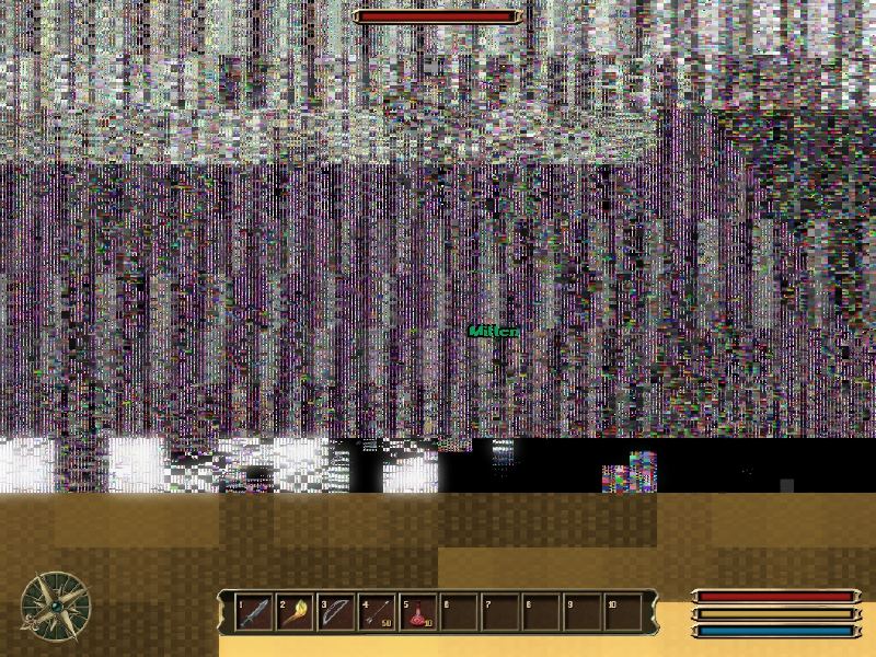
Be careful with making the clock frequency too high. The LCD's data interface has a maximum rate at which it can listen for new data. If you clock it too frequently you can corrupt the incoming data and LCD will may display pseudo-random noise.

Here's a screen shot from an "overclocked" LCD monitor:

enter image description here

\$\endgroup\$
2
  • \$\begingroup\$ Just delete all these comments and no one has to know! =P \$\endgroup\$ Commented Jan 21, 2013 at 10:07
  • \$\begingroup\$ What comments? :P \$\endgroup\$
    – user17592
    Commented Jan 21, 2013 at 11:29
1
\$\begingroup\$

Using a fixed oscillator to provide a clock signal for the data is a possibility, however it has a cost.

Whoever source the clock is the boss of timing, and everything else must comply with that timing.

If you use an external clock such as an oscillator (probably with some dividers), then the device sourcing the data must take that clock as an input and be sure that it always provides the data soon enough - which is to say a "setup time" before the active clock edge, plus any possibly clock skew between the source and destination. If you can make such a guarantee, it makes the job of designing the receiver very easy, since the receiver can add the requirement that the clock rate be steady.

Some devices such as digital-to-analog converters can have very harsh requirements for steadiness (formally, low jitter, or in communication terms, low phase noise) of the clock rate, and have their performance seriously impaired when that is not the case.

But other devices (especially those at relatively low rates and where data is just being received into a memory of some type - your LCD may be an example) can be perfectly fine with a clock that runs irregularlarly, for example in bursts. This can make the job of sourcing the data from software a lot easier, since the source can wait until it has data ready and present that data, before it activates the clock. With this type of interface, a very easy way of driving it from an older PC (at low to moderate data rates) was to use two data bits of the parallel port, and "bit bang" the data stream by explicitly asserting and de-asserting the clock and data signals in software. This would typically achieve the right relative timing (data valid before clock) but with a fair degree of variation in the overall timing. Unfortunately, this method does not work well with USB-connected I/O devices as the high latency of USB makes it slow, and it typically will not work at all with the data lines of USB-centronics printer adapters (though it may be possible with the control lines, or by acting more literally like a printer).

\$\endgroup\$

Your Answer

By clicking “Post Your Answer”, you agree to our terms of service and acknowledge you have read our privacy policy.

Not the answer you're looking for? Browse other questions tagged or ask your own question.