0
\$\begingroup\$

Two high-rep answers seem to have made the same misunderstanding, so to clarify:

  • My LED replacement tubes DO work with an existing, unchanged magnetic ballast. 2 fluorescent tubes out, 2 LED tubes in, and it works, just like the package says for the LED tubes. That's the baseline.
  • The same LED tubes DO NOT work with the second and third circuits drawn below. I've already tried those, with the results described next to the schematics.

Original text follows:


I have a bunch of 4-foot fluorescent fixtures with two tubes each. Two of them died recently. One with bad tubes and one with a bad magnetic ballast. I know it's magnetic because I took it apart and saw just enough "big iron" that wasn't covered by the potting material. I replaced the bad tubes with LED's, and they work wonderfully...or at least they did until I got the idea to rescue the other one with the bad ballast.


Looking at the "classic" schematic for a magnetic ballast with a single tube, I figured that there were 2 possibilities for the LED tubes:

  1. They're always in the "start" mode, which is supposed to power the heaters at each end of the tube before flyback-striking the arc when the bi-metal starter switch opens, or
  2. They're always in the "run" mode, which simply puts the line voltage across the length of the tube, with the inductor still in the circuit as a current limit
    (same idea as the capacitor in a "transformer-less" power supply, except that the imaginary part has the opposite sign (doesn't matter), and the same inductor also provides the flyback "kick" to get the arc started across the entire tube (that does matter))

enter image description here
(Image from Wikipedia)

I couldn't get a definitive schematic for a 2-tube magnetic ballast, or for the LED tubes, so I just went with the single-tube theory and figured I'd just wire two of those in parallel, permanently in either the "start" or "run" mode:


My first try was "run" mode, since that's how it is when it first receives power (failing that, the high voltage across the starter causes it to close, which switches it to "start" mode):
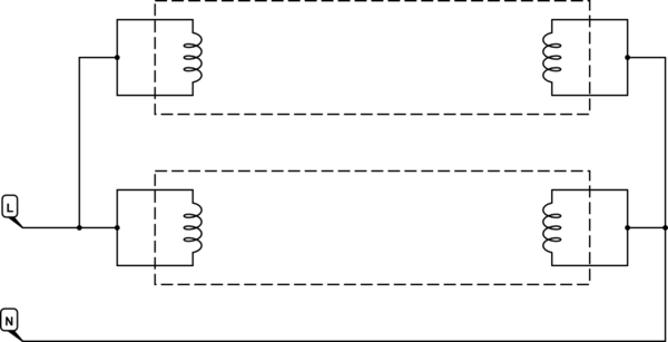
schematic

simulate this circuit – Schematic created using CircuitLab

A single LED tube, with the other socket left empty, flashed briefly and went out. I thought I had fried it, but when I put it back in the fixture that it came out of, that still had a good ballast, it came on again and stayed on.


Well, okay, so hard-wiring it for "run" mode as I understand it to be, minus the inductor, doesn't work. (LED's need a different kind of current control anyway, so the missing inductance shouldn't matter, right?)

So I rewired it to always be in "start" mode instead:
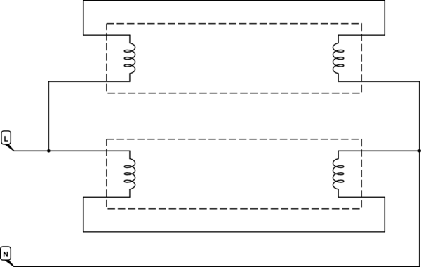
schematic

simulate this circuit

Exact same behavior. Leaving the other socket empty, a single LED tube flashed briefly and went out. Putting it back in the good fixture had it back on again, and staying on.


In both cases, I also tried the other LED tube, with the same results. After both configurations failed with both tubes, I noticed that they were both flickering in the good fixture, as if they were rectified with no filter, when I don't remember them doing that before. I suppose they could have been and I didn't notice, so this might not be an indicator of anything wrong.

I also noticed partway through the test, that the remaining tube in the good fixture was dimmer than when its neighbor was present. Not just the total light output being less because I took out half of the emitters, but the tube that I didn't touch also reduced its own output when its neighbor was removed. So the magnetic ballast is apparently doing something active, even with LED's instead of a 4-foot spark gap.


Since it seems that my understanding is a bit lacking here, what's really going on? Is the LED tube actually using the ballast's inductor as a current-limiting device, like the capacitor in a "transformer-less" power supply? If so, then I probably over-drove it...and triggered a self-protection thing perhaps, because it still worked in a "correct" fixture? I'd be surprised if these cheap things had anything more than the bare minimum required to work at all, but the box does say that they work with most fixtures, so... ¯_(ツ)_/¯

And is it possible to wire this up with no ballast at all, and have a pair of cheap LED tubes work reliably?
(I figured it was worth trying because the tubes are cheap enough to break some in the process of learning.)

\$\endgroup\$
5
  • \$\begingroup\$ Isn't a magnetic ballast literally just a big inductor? \$\endgroup\$
    – Hearth
    Commented Apr 4, 2021 at 2:19
  • 2
    \$\begingroup\$ AaronD, With the LED "fluorescent-replacement" tubes I've installed before, the ballast was removed from the fixture, entirely. I just cut it out and threw it away. In several refits, I can't recall any problems and they are still working okay. You've written a lot and I confess not reading most of it. Did you remove the ballast? Or not? Maybe this is just a USA thing here? \$\endgroup\$
    – jonk
    Commented Apr 4, 2021 at 2:44
  • \$\begingroup\$ @jonk The LED "fluorescent-replacement" tubes that I have, are apparently meant to keep the ballast in place. (minimal effort for the consumer) My experiment is to see if they also work with the ballast removed, as you describe, so that I can still use a fixture where the ballast has failed. \$\endgroup\$
    – AaronD
    Commented Apr 5, 2021 at 15:47
  • \$\begingroup\$ @Hearth Essentially yes, plus a starter switch that is a combination of a low-voltage spark gap and a bi-metal switch. And for low-voltage input, the inductor might also be a step-up auto-transformer. \$\endgroup\$
    – AaronD
    Commented Apr 5, 2021 at 16:15
  • \$\begingroup\$ The default state is "running", with the bi-metal switch open. When power is first applied, the tube is an open circuit end-to-end, so the starter gets the arc instead. This heats the switch enough to close it, which extinguishes that arc and powers the heaters at each end of the tube. The switch cools and eventually opens, at which point the inductive kick tries to strike an arc in the main tube. If that fails, the process repeats until it succeeds, at which point the inductor becomes simply a finite series impedance (mostly reactive) to control the current. \$\endgroup\$
    – AaronD
    Commented Apr 5, 2021 at 16:15

3 Answers 3

1
\$\begingroup\$

Read the datasheet for the LED tubes carefully. I suspect you will find they will take a full 240 VAC happily, or 115 VAC.

I have replaced several fluorescent fixtures now with LED tubes run directly from mains. One tube was a Phillips unit, several others were very cheap 'no-name' tubes. They were all rated for, and have run for a couple of years directly on, 240 VAC.

The instructions typically tell you to replace the old neon starter with a 'LED starter', which simply provides a fixed connection across the starter terminals. The LED tube accepts a high voltage across the terminals of one end, with the terminals at the other end having a fixed connection across them. This way, you can simply re-use the old fixture. The ballast will drop some voltage, but the tubes are built to accept a wide range of input voltage. When I tested, mine were still going strong at 75 VAC.

Whichever way round you connect the tube into a standard 240 V ballast fixture, you end up with the ballast in series with the tube electronics, via the dummy starter, and the tube's 'other end' connection. Obviously, with this many connections in series, there's the opportunity for a poor connection somewhere. Why was your fixture 'bad' in the first place?

There will often be a problem with 2-tube fixtures, and 115 V fixtures. The first can be designed to put the tubes in series, with corresponding changes to ballast and starter. The second can use a more complicated auto-transformer ballast to cope with the low input voltage. Both can potentially mess up the simple 'tube-replacement' way of using LED tubes.

Subject to the specifications, or markings on the tube, saying you can, you should be able to drive the tube directly from mains. To test a tube out of the fixture, you need to identify the 'power' end and the 'short circuit' end. The short circuit end will read 0 ohms on a multimeter. The power end may have a voltage marking on it (all my tubes did).

The safest way to repair an old bad fixture to take LED tubes is to identify a single circuit for each tube. Remove the ballast. Keep the two connectors wired in series, if the connectors are OK, so that you can plug the tube in either way round. If you choose like I did to provide full power to one end only, then you must make absolutely sure that you plug in the tube the right way round. Provide the fixture with a low value fuse, for when you inevitably plug it in wrong.

\$\endgroup\$
0
\$\begingroup\$

I think the heater type ballasts will be problematic with a dependency on two tubes working to load the ballast with an equivalent load.

I can’t guarantee a good soution to old ballasts of unknown condition to new LED ballast compatible tubes other than using new instant start no heater types.

I replaced all my old ballasts like this with Quad output ballasts that are independent so you can operate 1 to 4 FL tubes from 1 ballast. I extended the hot and common Yellow wires thru to the neighbouring fixture “tombstone” end connectors without difficulty. Although I chose tri-phosphor full spectrum FL 32W 4’ tubes 5000’K I believe these will work properly on LED tubes made to work from new ballasts. My tubes are 30k to 50k hr rated and have lasted 8 yrs so far with 86 lumens per watt and used twisted pairs to reduce EMI. In some cases like the garage, I just used the tombstone connectors PU glued and wired with 4 tubes over an 8’ span and works perfectly.

\$\endgroup\$
0
\$\begingroup\$

The fluorescent replacement people slowly are getting their act together. The latest is three types of replacement tubes: A, B, and C. Page 4 of this brochure explains the differences. I've been going through this with basement fixtures. Very few LED "tube lights" at Lowes or Home Depot are marked this way. Plus, some are marked that they will work with solid-state ballasts, but don't mention magnetic ballasts. GE has some marked explicitly for magnetic ballasts, but they are more expensive.

https://nunvdata.unvlt.com/uploads/Tubes_Selector_Guide.pdf

\$\endgroup\$
1
  • \$\begingroup\$ Mine are a different brand, but the closest match seems to be the power consumption of T8LDR4F15/8xxC and the light output of T8LDR4F12/8xxC. (slightly less efficient than your list) Definitely "Type A" (direct replacement, uses existing ballast) based on the instructions that came with them and the descriptions in your catalog, but the package doesn't actually say, nor do I see a UL mark. \$\endgroup\$
    – AaronD
    Commented Apr 5, 2021 at 15:56

Your Answer

By clicking “Post Your Answer”, you agree to our terms of service and acknowledge you have read our privacy policy.

Not the answer you're looking for? Browse other questions tagged or ask your own question.