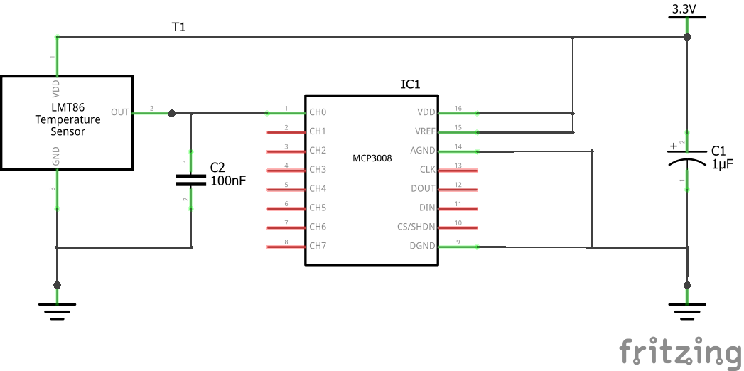
I'm currently working on a small project using LMT86 and MCP3008 as a temperature sensor for Raspberry Pi. The schematic is very simple:
So a couple of questions that I have:
The MCP3008 datasheet, "6.4 Layout Considerations" mentioned that The 3.3V power comes from the Raspberry Pi GPIO 3V3 pin. Is it necessary to use
C1to filter any potential noises? Or Raspberry Pi could guarantee that the 3V3 pin is noise-free?The LMT86 datasheet, "8.4.3 Capacitive Loads" states that
Without any precautions, the LMT86 can drive a capacitive load less than or equal to 1100 pF as shown in Figure 11.
And since the MCP3008 sample capacitor is only 20pF (page4), it should be okay without using a resistor between the LMT86 OUT and MCP3008 CH0. Did I read it correctly?
Regarding
C2, 9.2.1.1 Design Requirements said thatWhen the ADC charges the sampling cap, it requires instantaneous charge from the output of the analog source such as the LMT86 temperature sensor and many op amps. This requirement is easily accommodated by the addition of a capacitor, CFILTER.
And page3 said the "Analog Input Sample Time" is 1.5 clock, and page4 said the maximum "Clock Frequency" is 1.35MHz. Using a formula found here:
(R_on + R_out) * C_sample < 1 / resolution * T_sample, where:R_on = 1000Ω(page4, "Switch Resistance"),C_sample = 20pF(page4, "Sample Capacitor"),- resolution = 10bit,
T_sample= 1 / 1.35MHz (the actual SPI clock is only 0.1MHz with theadafruit_blinkadriver),- Although I didn't find the correct number of
R_out, by testing I knew that LMT86 OUT pin generally has about 1~2V in my use case, and the max output current is 7mA (page5), so I guessR_outis a couple of hundred to one kilo ohms. TakeR_out = 1kΩ
then
(R_on + R_out) * C_sample = (1000 + 1000) * 20e-12 = 4e-8, and1 / 100 * T_sample = 0.1 * 1.35e-6 = 13.5e-8, so the formula holds even with the maximum clock frequency MCP3008 supports.So my question is, does this mean
C2is unnecessary?My tests showed that using or not using
C2yields the same result.

