I am trying to set up an Arduino as DALI-Master for multiple light sources. As a starting point I made use of this excellent project. There is also a gitpage with a good overview of the available commands. I rewrote the code to to send commands directly after initializing.
#include <Arduino.h>
#include <Dali.h>

//#include<Logger.h>
bool DEBUGLOG = 1;

uint8_t MODE = 0;
uint8_t OK = 0;

#define BROADCAST_DP 0b11111110
#define BROADCAST_C 0b11111111
#define ON_DP 0b11111110
#define OFF_DP 0b00000000
#define ON_DP1 0b00111111
#define ON_DP2 0b11010100
#define ON_DP3 0b11100001
#define ON_C 0b00000101
#define OFF_C 0b00000000
# define QUERY_STATUS 0b10010000
# define RESET 0b00100000

void setup() {
  Serial.begin(9600);

  dali.setupTransmit(3);
  dali.setupAnalogReceive(A7);
  dali.busTest();
  dali.msgMode = true;

  //Logger::log("--- Dali EXP ---");
  Serial.println("--- Dali EXP ---");
}

bool scanByte(byte &result) {
  bool byteArr[8];
  bool ERR = 0;
  bool scandone = 0;

  while(Serial.available()) {
    // byte _temp = Serial.read();
    // Serial.print("-");Serial.print(_temp);Serial.print("-");

    uint8_t _temp = Serial.read();
    // Logger::log("-",_temp);

    if(_temp==124) { // begin scan

      for(int n=7;n>=0;n--) {
        uint8_t temp = Serial.read();

        if(temp==49) {
          byteArr[n] = 1;
        } else if(temp==48) {
          byteArr[n] = 0;
        } else {
          ERR = 1;
        }

      }

      scandone=1;
    }
    // else if(_temp==88) {
    //   MODE=0;
    //   Serial.println("X");
    //   return false;
    // }

    if(scandone) {
      if(Serial.read()==124) { // end scan
        result = 0;
        for(int i=0;i<8;i++) {
          if(byteArr[i]) {
            result = result | (1<<i);
          }
        }

        if(ERR) {
          return false;
        } {
          return true;
        }
      }
    }
  }

  return false;
}

bool dimmer = false;
uint8_t dimlevel = 0b00000101;

void loop() {

  String comMsg;

  if(MODE==0) {

    while(Serial.available()) {
      comMsg = comMsg + (char)(Serial.read());
    }

    if(comMsg == "C") {
      MODE = 1;
      Serial.print("C");
      comMsg = "";
    }
    if(comMsg == "X") {
      MODE = 0;
      Serial.print("X");
    }

    if(comMsg == "ini") {
      Serial.println(comMsg);
      dali.initialisation();
    }
    if(comMsg == "scan") {
      dali.scanShortAdd();
    }
    if(comMsg == "response") {
      bool res = dali.getResponse;
      //Logger::log("Response: ");
      Serial.print("Response: ");
      Serial.println(res);
    }
    if(comMsg == "help") {
      //Logger::log("help");
    }
    if(comMsg== "on") {
      dali.transmit(BROADCAST_C, ON_C);
    }
    if (comMsg == "off") {
      dali.transmit(BROADCAST_C, OFF_C);
    }
    if (comMsg == "dimoff") {
      dimlevel = 0;
      dimmer = false;
      Serial.print("OFF: dim = "); Serial.println(dimlevel);
      dali.transmit(BROADCAST_DP,OFF_DP);
    } else if(comMsg == "dim1") {
      dali.transmit(BROADCAST_DP,ON_DP1);
    } else if(comMsg == "dim2") {
      dali.transmit(BROADCAST_DP,ON_DP2);
    }  else if(comMsg == "dim3") {
      dali.transmit(BROADCAST_DP,ON_DP3);
    }  else if(comMsg == "dim4") {
      dali.transmit(BROADCAST_DP,ON_DP);
    } else if(comMsg == "dimon") {
      dimlevel = 10;
      dimmer = true;
      Serial.print("ON: dim = "); Serial.println(dimlevel);
      dali.transmit(BROADCAST_DP,dimlevel);
    } else if(comMsg == "up" && dimmer) {
      dimlevel += 5;
      Serial.print("dim = "); Serial.println(dimlevel);
      dali.transmit(BROADCAST_DP,dimlevel);
    } else if(comMsg == "down" && dimmer) {
      dimlevel -= 5;
      dali.transmit(BROADCAST_DP,dimlevel);
      Serial.print("dim = "); Serial.println(dimlevel);
    }

  }

  if(MODE==1) {

    if(Serial.available()) {

      byte result,result1;
      OK = scanByte(result);
      OK &= scanByte(result1);

      if(OK) {
        Serial.print(result,BIN); Serial.print(" "); Serial.println(result1,BIN);
        // Logger::log("result  = ",result,BIN);
        // Logger::log("result1 = ",result1,BIN);

        dali.transmit(result,result1);
        uint8_t resp = dali.receive();
        Serial.print("Respons: "); Serial.print(resp); Serial.print(" "); Serial.println(resp,BIN);
      }

      Serial.flush();

    }


  }


  delay(250);
}
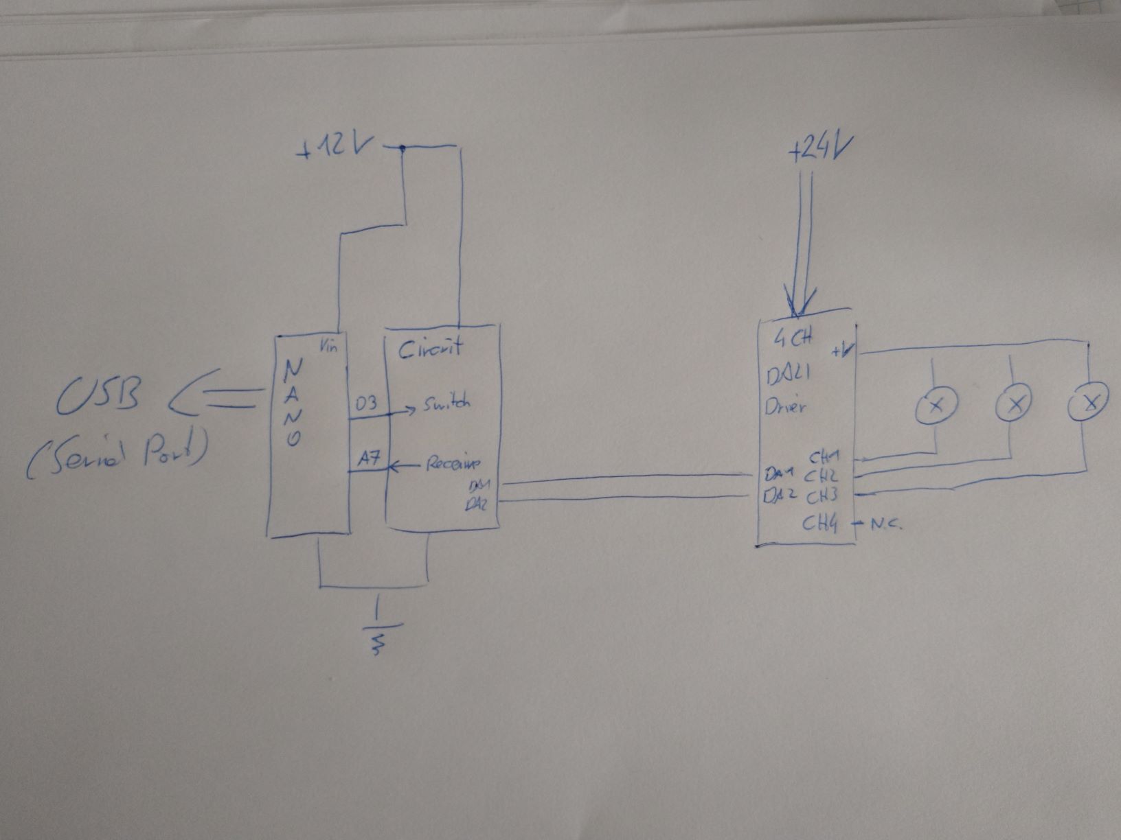
My current setup is shown in the picture below. The circuit is the same as in the tutorial. The transistor is replaced with standard 2N2222A . Sending and receiving commands works even with the 12V. The library used is found here
One of the LED drivers is a Skydance 4Channel constant voltage driver (link). Every channel should have its own DALI address.
After startup I can use the commands "ini" send the startup commands, "scan" to look for the available addresses on the bus, "on\off" to send the on/ off command to all bus members. With the input command "C" I can switch to command mode and enter commands in binary form
|YAAAAAAS||xXxXxXxX|
After initiation and scanning I only get one addresses
--- Dali EXP ---
Short addresses:
BIN: 0 DEC: 0 HEX: 0 Get response
BIN: 1 DEC: 1 HEX: 1 No response
BIN: 10 DEC: 2 HEX: 2 No response
BIN: 11 DEC: 3 HEX: 3 No response
BIN: 100 DEC: 4 HEX: 4 No response
BIN: 101 DEC: 5 HEX: 5 No response
BIN: 110 DEC: 6 HEX: 6 No response
BIN: 111 DEC: 7 HEX: 7 No response
BIN: 1000 DEC: 8 HEX: 8 No response
BIN: 1001 DEC: 9 HEX: 9 No response
BIN: 1010 DEC: 10 HEX: A No response
BIN: 1011 DEC: 11 HEX: B No response
BIN: 1100 DEC: 12 HEX: C No response
BIN: 1101 DEC: 13 HEX: D No response
BIN: 1110 DEC: 14 HEX: E No response
BIN: 1111 DEC: 15 HEX: F No response
BIN: 10000 DEC: 16 HEX: 10 No response
BIN: 10001 DEC: 17 HEX: 11 No response
BIN: 10010 DEC: 18 HEX: 12 No response
BIN: 10011 DEC: 19 HEX: 13 No response
BIN: 10100 DEC: 20 HEX: 14 No response
BIN: 10101 DEC: 21 HEX: 15 No response
BIN: 10110 DEC: 22 HEX: 16 No response
BIN: 10111 DEC: 23 HEX: 17 No response
BIN: 11000 DEC: 24 HEX: 18 No response
BIN: 11001 DEC: 25 HEX: 19 No response
BIN: 11010 DEC: 26 HEX: 1A No response
BIN: 11011 DEC: 27 HEX: 1B No response
BIN: 11100 DEC: 28 HEX: 1C No response
BIN: 11101 DEC: 29 HEX: 1D No response
BIN: 11110 DEC: 30 HEX: 1E No response
BIN: 11111 DEC: 31 HEX: 1F No response
BIN: 100000 DEC: 32 HEX: 20 No response
BIN: 100001 DEC: 33 HEX: 21 No response
BIN: 100010 DEC: 34 HEX: 22 No response
BIN: 100011 DEC: 35 HEX: 23 No response
BIN: 100100 DEC: 36 HEX: 24 No response
BIN: 100101 DEC: 37 HEX: 25 No response
BIN: 100110 DEC: 38 HEX: 26 No response
BIN: 100111 DEC: 39 HEX: 27 No response
BIN: 101000 DEC: 40 HEX: 28 No response
BIN: 101001 DEC: 41 HEX: 29 No response
BIN: 101010 DEC: 42 HEX: 2A No response
BIN: 101011 DEC: 43 HEX: 2B No response
BIN: 101100 DEC: 44 HEX: 2C No response
BIN: 101101 DEC: 45 HEX: 2D No response
BIN: 101110 DEC: 46 HEX: 2E No response
BIN: 101111 DEC: 47 HEX: 2F No response
BIN: 110000 DEC: 48 HEX: 30 No response
BIN: 110001 DEC: 49 HEX: 31 No response
BIN: 110010 DEC: 50 HEX: 32 No response
BIN: 110011 DEC: 51 HEX: 33 No response
BIN: 110100 DEC: 52 HEX: 34 No response
BIN: 110101 DEC: 53 HEX: 35 No response
BIN: 110110 DEC: 54 HEX: 36 No response
BIN: 110111 DEC: 55 HEX: 37 No response
BIN: 111000 DEC: 56 HEX: 38 No response
BIN: 111001 DEC: 57 HEX: 39 No response
BIN: 111010 DEC: 58 HEX: 3A No response
BIN: 111011 DEC: 59 HEX: 3B No response
BIN: 111100 DEC: 60 HEX: 3C No response
BIN: 111101 DEC: 61 HEX: 3D No response
BIN: 111110 DEC: 62 HEX: 3E No response
BIN: 111111 DEC: 63 HEX: 3F No response
Sending commands to the address '0' changes the behavior of all ballasts on the driver simultaneously. For example:
|00000001||00000001|
sends the command for 'UP'. Here, all ballasts increase their brightness. It looks like the driver is assigned one address instead of four. When scanning for the short addresses each lamps lights up individually (like a sweep), which suggests that every channel can be controlled individually.
After connecting a second (cheap) DALI-driver and one ballast to it my test setup is now:
- DALI_1: 3 Ballasts
- DALI_2: 1 Ballast
- 16.5V Busvoltage
- 1.5mm2 cable for the bus cables
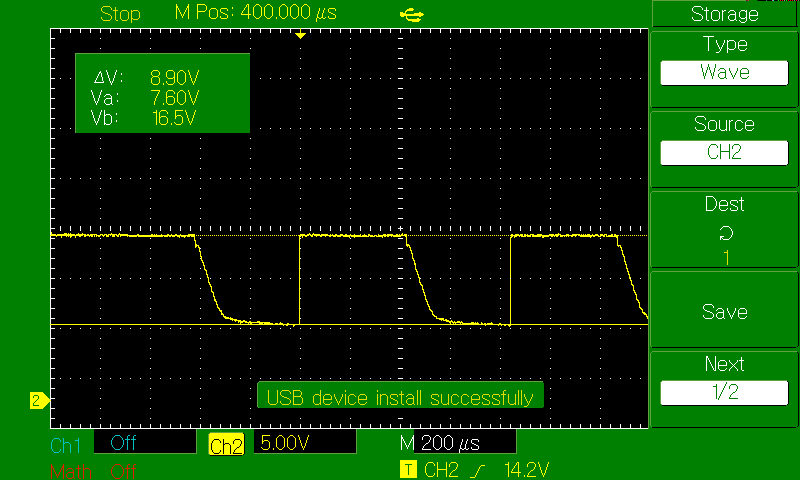
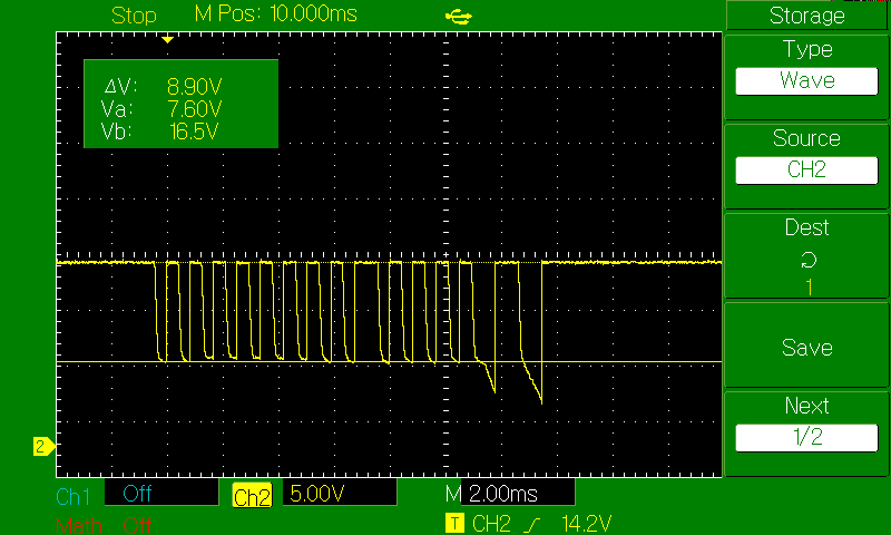
The signal for the "ON" command looks like


Now no channels (or drivers) are detected, but the ON\ OFF goes through.
How can I initialize each channel? Are the edges of the signal flanks to rough in order to detect it by the drivers? Why are 'broadcast to all' commands work, but initializing only sets one address for all channels?


