0
\$\begingroup\$

First at all, thank you so much for all the answers I have received on all the threads. Well, I'm working on PCB Raspberry Compute Module 4 Carrier including USB 3.0 Controller (TUSB7320) using PCIE lines. I have inspected this layout guide:

https://www.ti.com/lit/ug/sllu149e/sllu149e.pdf?ts=1619089469669&ref_url=https%253A%252F%252Fwww.ti.com%252Fproduct%252FTUSB7320

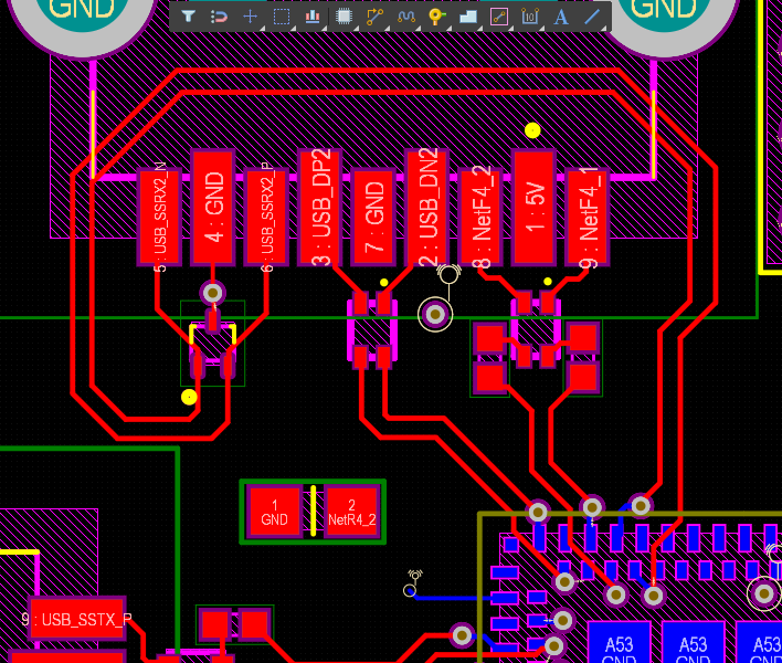
But It create some doubts about priorities of rules. TI recommends reduce the number of vias and reduce the length of the traces. What is the stronger rule? In the first picture I avoid using more vias incrementing the length (much less than the maximum length that TI recommends). What is better?

Avoiding put more vias

On this picture I can't use narrower traces (I would need 0.10 mm width trace to put the trace between pads) so the number of vias is not equal for these two lines. Should I to create 2 vias to change the layer and matching the length for the two layers? Inequal number of vias

\$\endgroup\$

1 Answer 1

0
\$\begingroup\$

When routing USB 3 signals, the strongest rule is "length of the traces".


On this picture I can't use narrower traces (I would need 0.10 mm width trace to put the trace between pads) so the number of vias is not equal for these two lines. Should I to create 2 vias to change the layer and matching the length for the two layers?
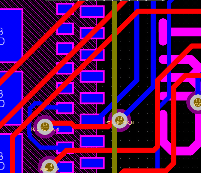
0.1 mm (4 mils) trace width is fine. That's not going to pump up the PCB price.

Yet, shrink by 1 mil the width of the 2 pads of the connector, don't create vias, and route the signal between the 2 pads of the connector.

At the end, match the traces length.

\$\endgroup\$
2
  • \$\begingroup\$ Thank you so much! And there is not problem with the routing style of the first picture? Is it the best option? \$\endgroup\$
    – Juanma
    Commented Apr 22, 2021 at 13:06
  • 1
    \$\begingroup\$ I see a problem: the metal case of the connector might short the 2 pairs of traces, when pressed down. It happened to me 20 years ago with a DB9 connector. Make sure the metal case of the connector doesn't touch those PCB traces. \$\endgroup\$ Commented Apr 22, 2021 at 16:44

Your Answer

By clicking “Post Your Answer”, you agree to our terms of service and acknowledge you have read our privacy policy.

Not the answer you're looking for? Browse other questions tagged or ask your own question.