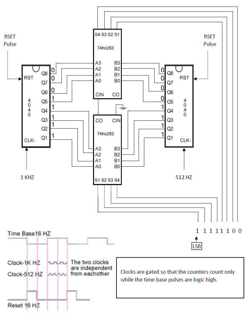
I am experimenting with a circuit for adding two numbers represented by two digital counters and two cascaded 4 bits adders (74HC283). I tested separately with cascaded 74HC163 and with asynchronous 74HC4040 counters and I ended up with the same results.
I feed one of the counters with a 1 kHz com signal and the second counter with 512 Hz signals. All signals are well formed square signals.
I use a 16Hz crystal-controlled time base. The counters count during logic high of the time base that is 1/32 second or about 31 milliseconds. The counters are reset in the second half of the logic-low of the time base.
When I verify the outputs of the first counter, my oscilloscope shows pulses at some of the outputs and I consider them as logic high. The output of the first counter is binary 00011111 to represent the 1kHz clk input, almost as expected. The output of the second counter is binary 00001111 to represent the 512 Hz clk input also during the 1/32 sec. So far so good because I can read the output of the counters correctly.
I feed input a[] of the cascaded adders by the outputs of the first counter and input b[] of the adders by outputs of the second counter. I expect to see the same pulsing output pins of the adders to show the correct sum. My expectation is to see the correct sum as the binary number 00101110 at output s[] of the 8 bits adder, the same way that I see the correct binary numbers at the pulsing pins of the two counters.
Instead, I see binary 00111111 as the sum.
If I change the clk input of the first counter to 2kHz and I leave the clk input of the second counter as it was 512 Hz, I see binary number 01111111 instead of the correct sum 01001110 as sum at outputs s[] of the adder.
If I change the clk input of the first counter to 512kHz like the second counter, I see the correct output of 00011110 as sum at outputs s[] of the adder.
I understand that as the counter is cycling through the addition is performed. My thoughts are that the total propagation delay of the counters and the adders is in the order of hundreds of nanoseconds but the counters are not counting for many milliseconds before they are reset.
My expectation is to see the correct sum at output s[] of the adder at their pulsing output pins while the counters are counting during the logic high of the time base.
I mean, I expect to see the right output of the adders at their pulsing output pins just like I can see the right output of the counters at their pulsing output pins. Is my expectation justified while counters periodically pause counting? If so, why do I get the wrong sum?
Please note that it is not about what kind of counters I am using. It is about the wrong sum no matter which counter I use.

