1
\$\begingroup\$

I am getting into circuits and trying to improve my knowledge but even though it might sound like a silly question but here is my story short:

What I am trying to do

I am building a circuit to drive an LED strip (12v) out of a Raspberry Pi using PWM output.

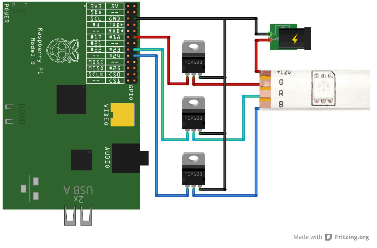
It worked out perfectly using a TIP120 on the breadboard using the following example:

enter image description here

My goals

Now that it is working, I am building a PCB to send to JLCPB to have it printed and assembled so I wish to use basic parts as much as possible and ended up selecting a D882 transistor which is not a Darlington. I heard that it might cause issues to my actual circuit and not expecting the same result as with the TIP120.

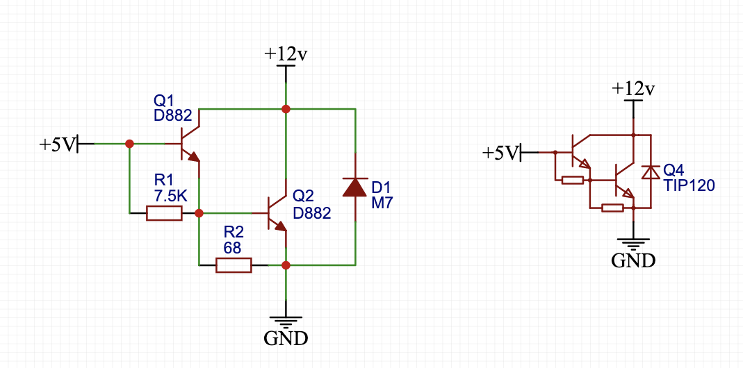
So a using D882 transistor I kind of recreated the schematic of the TIP120.

Am I silly to say that this will do the same thing as the TIP120?

enter image description here

Am I in the wrong way and another SMD component would do the trick?

Update

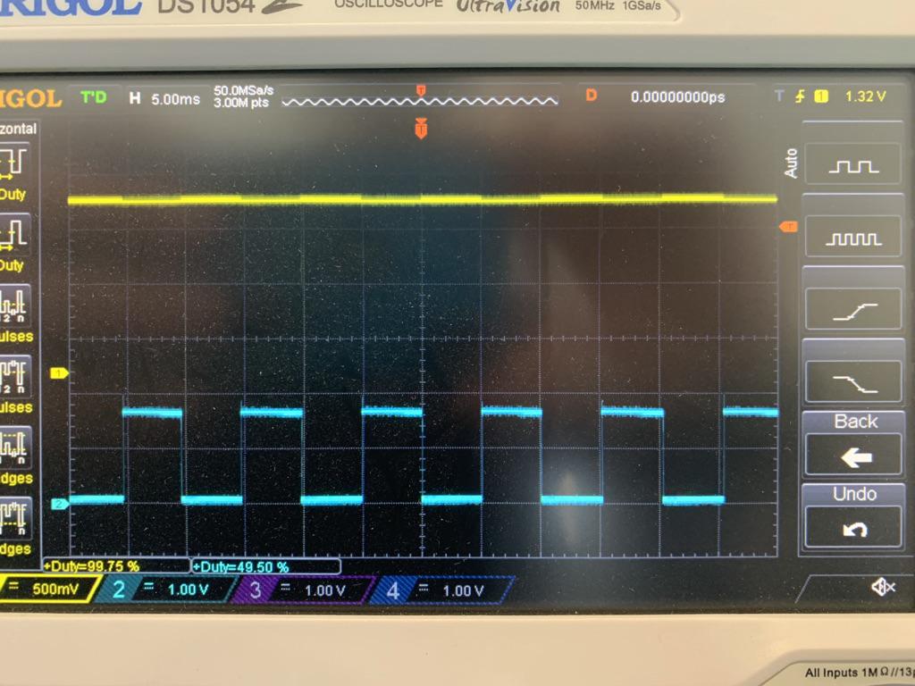
Channel 1 at 100%, seem to get alot of noise but Channel 2 at 50% is quite stable.

enter image description here

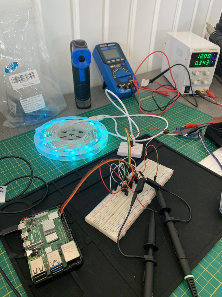
Here you can see the quick simple prototype

enter image description here

\$\endgroup\$
12
  • \$\begingroup\$ Unfamiliar with RPi: are those outputs current limited? If not you definately need to add a base resistor. \$\endgroup\$ Commented Apr 23, 2021 at 16:07
  • \$\begingroup\$ Yes, they are limited to 5v. \$\endgroup\$
    – maxleb
    Commented Apr 23, 2021 at 16:17
  • \$\begingroup\$ Both schematics are insufficient due to lack of base current limiting R missing and voltage rise when saturated on output. It is better to use open drain power FETs for interfacing 12V LEDstrips . or two stage inverting BJTs PNP+NPN with proper R values to reduce Vce(sat) <0.4V vs 1.7V @ 3A on your choices, you must specify load current and output max current you choose from Rpi. \$\endgroup\$
    – D.A.S.
    Commented Apr 23, 2021 at 16:24
  • 2
    \$\begingroup\$ @maxleb Current is not expressed in Volts... \$\endgroup\$ Commented Apr 23, 2021 at 16:39
  • \$\begingroup\$ @maxleb You've already said that the TIP120 works well for your needs. This tells us that you don't need all of the +12 V supply potential because the TIP120 drops about 1.5 V of it. You are now in a position where you don't want to specify the TIP120 but want, instead, to design a replacement that meets additional requirements. At this point, I think we need to know more about the worst case current compliance needed and I think you need to re-evaluate the voltage drop (because in a new design you get to do that.) And what PWM rate are you using and what's the dynamic range of the duty cycle? \$\endgroup\$
    – jonk
    Commented Apr 23, 2021 at 17:03

1 Answer 1

0
\$\begingroup\$

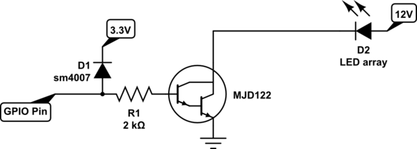
If you just need a surface mount version of a tip120, the MJD122 would work, but I would recommend the fallowing to protect your GPIO from the 12V, which is 3.3V i/o on a raspberry pi.

schematic

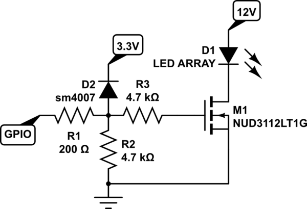
simulate this circuit – Schematic created using CircuitLab But either way, the efficiency of using a transistor with this micro controller board is not going to be that good to begin with. Now, if we use an enhancement mode MOSFET instead of a darlington, then the low voltage cmos from the raspberry pi (2.5V logic hi) would drive the circuit efficiently, and more like a switch. So I would recommend for raspberry pi, this kind of driver circuit:

schematic

simulate this circuit

\$\endgroup\$
5
  • \$\begingroup\$ Vce(sat)=2Vmax @ 4A for Ib=16mA yet for Vout=3.3V and Vb= ~1.2V to 1.5V your Rb=2k only provides 1.8V/2k <1mA to 1.1V/2k= 0.55mA so with a saturated hFE of only 250 , it can drive about 130mA , your Vce(sat) might rise to 3V with more current reducing LED brightness. Not a great solution but will turn on lights \$\endgroup\$
    – D.A.S.
    Commented Apr 23, 2021 at 17:04
  • \$\begingroup\$ That is why enhance mode mosfets would be a better choice in this application @TonyStewartEE75 instead of a darlington transistor. Because the Raspberry pi are low voltage cmos outputs. Even reducing the safety resistor to its minimum at 1K is still not really enough drive. 2.5V logic hi. But I guess the OP is wanting to use a transistor driver. On other micro controllers that are TTL level, this is not an issue \$\endgroup\$ Commented Apr 23, 2021 at 17:13
  • \$\begingroup\$ Yes I suggested FETs in comments to avoid the problems not clarified in your answer. For this application. \$\endgroup\$
    – D.A.S.
    Commented Apr 23, 2021 at 17:17
  • \$\begingroup\$ I added a MOSFET circuit just in case the OP wants a better solution for his app. \$\endgroup\$ Commented Apr 23, 2021 at 17:41
  • \$\begingroup\$ Thanks @DavidMikeska, as I don't have those parts in stock I will test it out as you mentionned as soon as I get the missing parts. Good enough for an accepted answer. \$\endgroup\$
    – maxleb
    Commented Apr 23, 2021 at 18:27

Your Answer

By clicking “Post Your Answer”, you agree to our terms of service and acknowledge you have read our privacy policy.

Not the answer you're looking for? Browse other questions tagged or ask your own question.