1
\$\begingroup\$

I'm designing a TTL to VGA DAC for a vintage PC, and I'm confused about the significance of the output and input impedances of my video card and monitor, respectively. The VGA spec states 75 ohms at both ends, if I understand it correctly. I couldn't find mention of an output impedance for the TTL video cards (I have an IBM CGA card and an IBM MDA card). My first inclination is to treat both the card and the monitor as 75 ohm equivalent resistors, and design accordingly. Specifically, my diagram would look like this:

schematic

simulate this circuit – Schematic created using CircuitLab

But on further consideration, it occurs to me that the video card is TTL, so there should be 5V on the signal lines, and I can just ignore its output impedance and treat it like a straight 0V/5V signal source. In that case, my diagram would be the same, except it would omit R1.

The contents of the solid box is just a resistor network, to combine the digital rgbi lines into an analog signal and drop the voltage down from 5V to .7V max, as per the VGA spec. No active components, transistors, diodes or other fancy stuff.

Am I thinking about this correctly, or am I going to set fire to something?

\$\endgroup\$
4
  • \$\begingroup\$ Seems pointless, since CGA and MDA signal timings are not compatible with VGA. How do you intend to deal with that? \$\endgroup\$ Commented Apr 24, 2021 at 12:27
  • \$\begingroup\$ TTL chips have very poor output impedance. They can sink a moderate amount of current, but can only source maybe around 1 mA. But there is really no point converting CGA, MDA or EGA digital signals to analog, as even if you did buffer them and have good analog video, almost no monitor would accept the signal due to horizontal line rate. You need a scan converter, and hobbyists have already made these with FPGAs. \$\endgroup\$
    – Justme
    Commented Apr 24, 2021 at 12:28
  • \$\begingroup\$ Here's one monitor that does CGA, EGA and VGA for US$450 - ouch! converters.tv/vga_to_vga/… \$\endgroup\$ Commented Apr 24, 2021 at 13:48
  • \$\begingroup\$ texelec.com/product/mce2vga \$\endgroup\$ Commented Apr 24, 2021 at 13:50

2 Answers 2

1
\$\begingroup\$

it occurs to me that the video card is TTL, so there should be 5V on the signal lines,

You cannot assume the outputs will go up to 5 V, only that they will meet the TTL minimum output levels of 2.4 V high and 0.8 V low, when loaded with TTL inputs. CGA and MDA cards often used bipolar TTL chips that pull up weakly to ~3.5 V, with exact values depending on the particular logic family and IC.

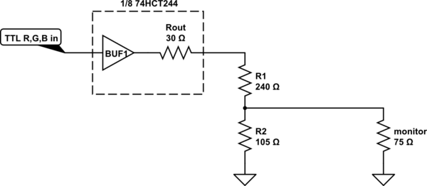
To guarantee a stable output voltage and impedance you should buffer the TTL signals with TTL compatible high speed CMOS Logic, preferably a line driver such as 74HCT244 which has strong output drive (need ~9 mA to drive 75 Ω to 0.7 V).

With normal cable length an exact impedance match is not required, but getting the correct level is. A single series resistor with value adjusted to get 0.7 V with 75 Ω termination should be sufficient. For a closer impedance match you could use an 'L' pad, like this:-

schematic

simulate this circuit – Schematic created using CircuitLab

\$\endgroup\$
0
\$\begingroup\$
  1. First of all you should think inn terms of equivalent circuits of the sources, i.e. Thevenin circuit. So, your TTL source has in principle a 0-5 V signal excursion (although there are internal voltage drops and limited capabilities to go rail to rail), but combined with a series impedance. The circuit is indeed non-linear and we need to simplify a bit: a voltage source with ideally a square wave and a series resistance is suitable. Which value for the resistance: it depends on the TTL family, and considers also that the values are in reality different for 0->5V ad 5->0V transitions. See past post o this site: Input and Output Impedance of a TTL NAND Gate A good guess may be at about 100ohm.

  2. The you draw the circuit as a single-line combination of components, all in series. Take into consideration that there are series resistance, but also shunt resistance to ground.

  3. The load is 75ohm, and if you connect the source and the load with a cable, or a log transmission line, this must have 75 ohm characteristic impedance to avoid reflections.

  4. The network you put in your box should be better detailed. It will have an input impedance (resistance), that "sees" the source and its more-or-less 100 ohm, and an output impedance that "sees" the 75 ohm load. Somewhere there is the cable or transmission line, possibly between the network-in-the-box ad the load. So that network should also be approximately matched to the 75 ohm at its output. For the matching at the input, if you do not have a feeding line but the source is directly connected, you might have some voltage drop but no serious reflections.

\$\endgroup\$
2
  • \$\begingroup\$ A typical LS244 has Voh of 2.4V guaranteed at 3mA current out. The impedance is more closer to 860 than 100 ohms. \$\endgroup\$
    – Justme
    Commented Apr 24, 2021 at 14:26
  • \$\begingroup\$ That is a resistance (static). Dynamic impedance is less. Just take the output stage and mentioned collector resistance as example at the link above electronics.stackexchange.com/questions/503178/…. Caveat : the circuit is on linear. \$\endgroup\$
    – andrea
    Commented Apr 24, 2021 at 19:25

Your Answer

By clicking “Post Your Answer”, you agree to our terms of service and acknowledge you have read our privacy policy.

Not the answer you're looking for? Browse other questions tagged or ask your own question.