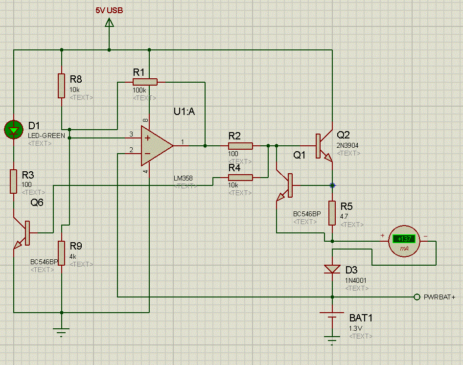
Your circuit looks like it should do exactly what you want it to
AND you say in your response to Chintalagirl that it does what you intend re cutoff voltage and hysteresis
SO I cannot understand what you want that you do not already have.
I recently implemented a commercial circuit for highish volume production using a circuit similar tothis one. It used a diode to allow low level voltage under hysteresis feedback to be set without altering trip voltage and used a TL431 to provide a more stable reference voltage - both as mentioned below.
V_USB cannot be reliably guaranteed to be 5V and may be higher or lower and may vary so a proper reference is needed. You can eg divide R8 into two parts and set the middle point at say 4V using eg a TL431 "programmable zener" / shunt regulator. These are cheap and effective in this role. Using a TLV431 allows 1.25V on up reference setting.
Better - you can set U1A pin3 AT the desired trip voltage with the TL431 BUT then the hysteresis feedback does not work so you can eg.
Use a TL*V*431 with two resistors to set it to desired Vtrip.
Feed the TLV431 with about 1k to cathode from V_USB.
Feed TLV431 via say 10k to opamp non inverting input.
Use 100k or whatever hysteresis resistor as before with series diode. See below.
Using R1 as shown makes it hard to set high and low thresholds as desired as effectively R1 is in parallel with R8 before the battery reaches the trigger point and in parallel with R9 after the trigger point is reached so high and low set points are affected. Also, if the op amp does not swing to high rail fully it will affect the trip point calculation. Easier and just as effective is to place a diode in series with R1 so it conducts with only one opamp polarity so that either the high or low threshold is set only by R8 & R9. Best probably is to connect diode cathode to U1A output so that the diode conducts when the threshold has been reached and so then lowers the threshold when U1A output goes low. That way you can accurately set the desired trip point with R8 & R9 (which is what you most care about) and then R1 will lower this somewhat by an amount that you can calculate. The diode adds a small amount of complexity to the calculation of the lowered threshold but it is not very important as the main object is to terminate charging.
If R1 is too large the threshold will not be lowered enough and the battery voltage may "sag" enough after charge is removed to cause charging to restart. If you observe this with a meter and not with a scope you may think that you are seeing a stable DC voltage but really the circuit is oscillating. (Ask me how I know :-) ).
Inspection with an oscilloscope is always an extremely good idea with circuits like this as oscillation may easily occur.
It should not matter here but be aware that input common mode range for the LM358 is 1.5V below Vdd so here Vin max ~= 3.5.
Once you have added the diode suggested above you can test trip point by measuring at U1A pin 3. You can have R8 or R9 adjustable to set trip point. You can check correct operation by using a low leakage capacitor in place of the battery. This should charge to Vtrip and the circuit should then turn off and Vcap should equal target voltage. If the cap leaks you will see it recharge occasionally as Vcap falls below the lower threshold.
Q1 / R5 is a nasty way to do current setting as the Vbe reference is very imprecise - but it is good enough in this application. D3 is probably not strictly ncessary here but should do no harm. Without D3 Q1 and Q2 are potentially reverse biased by battery when the transistor is off but it should not be a problem here.
R1 hysteresis should stop this circuit settling into liner mode when setpoint is reached, especially with the diode added, but do check for oscillation. Usually adding a capacitor somewhere in either the drive or feedback loops will help. eg here U1A pin 3 might have a cap to ground BUT a better place would be pin 2, with the feed to pin 2 from the battery being via eg a 10k resistor. You can either express this in formal circuit theory pole/zero nomenclature or can see it as a delay in the rate at which the sensed battery voltage may change.
Ask as required ...


