0
\$\begingroup\$

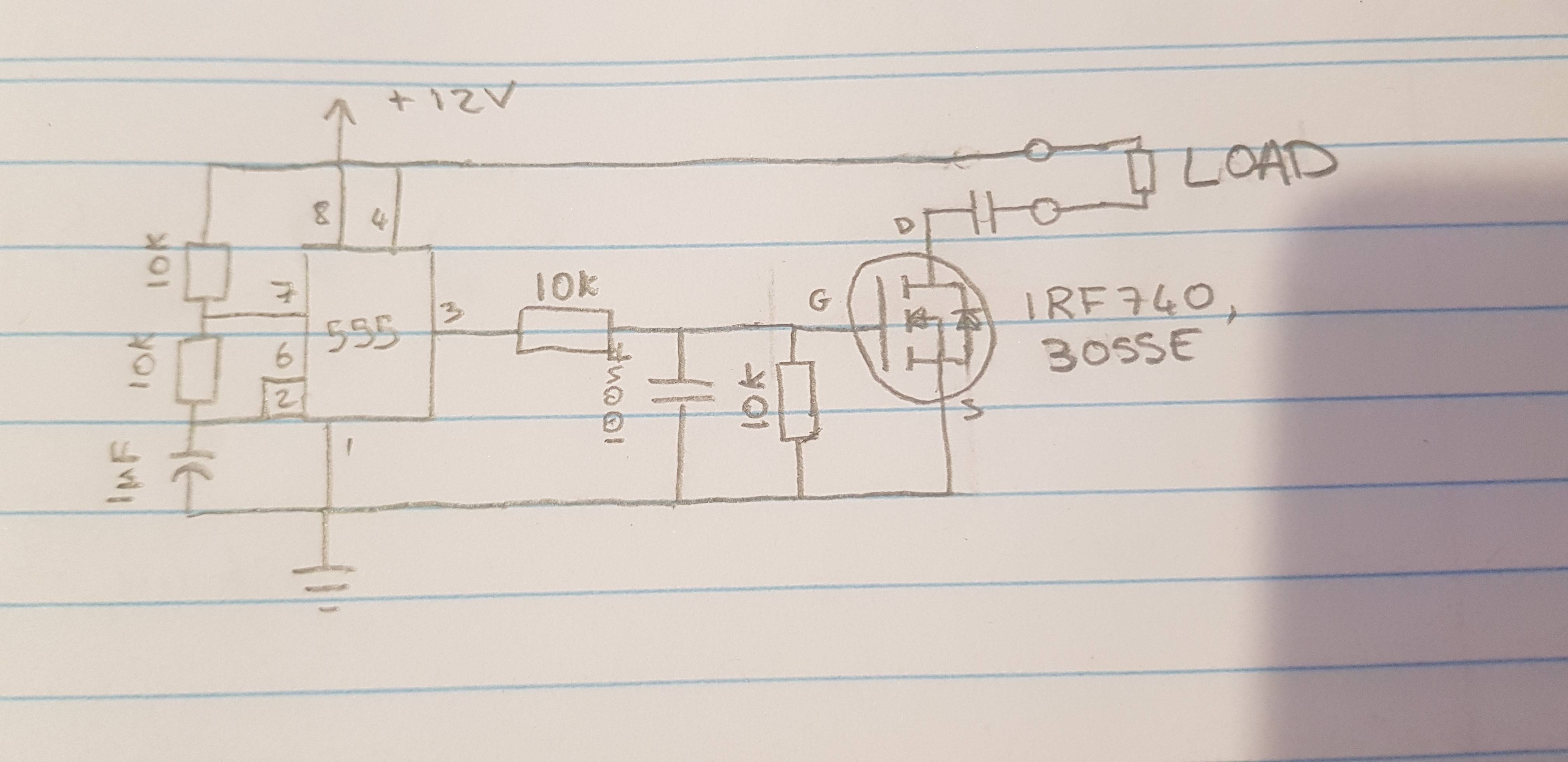
Some background. I am attempting to build a oscillator circuit for use in HV power supply. Using a 555 to create a PWM to switch a MOSFET and then to either transformer or buck converter.

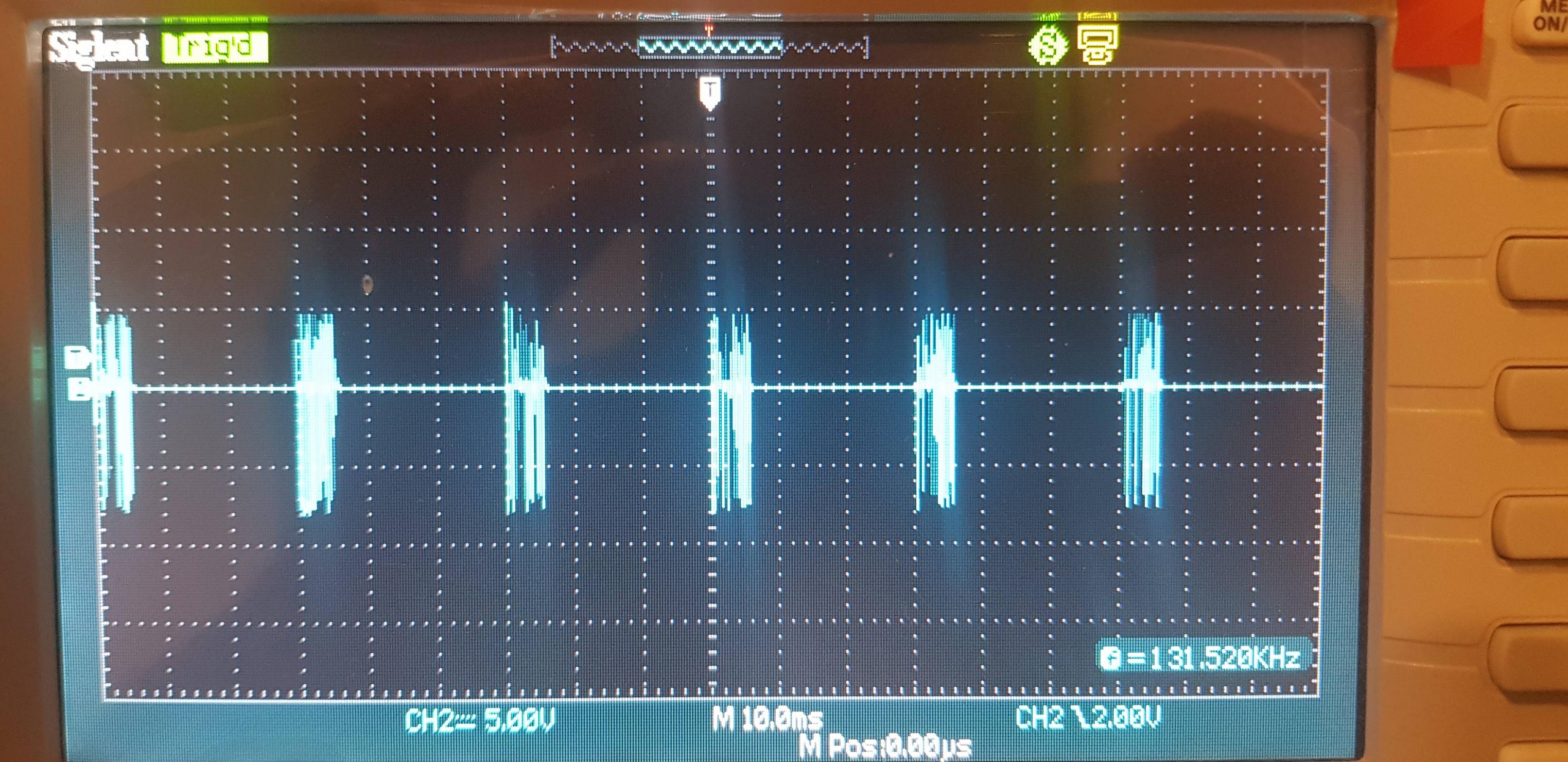
I have gotten the 555 to produce a clean square signal but the waveform output of the MOSFET is not a square wave. It is this: Output of MOSFET
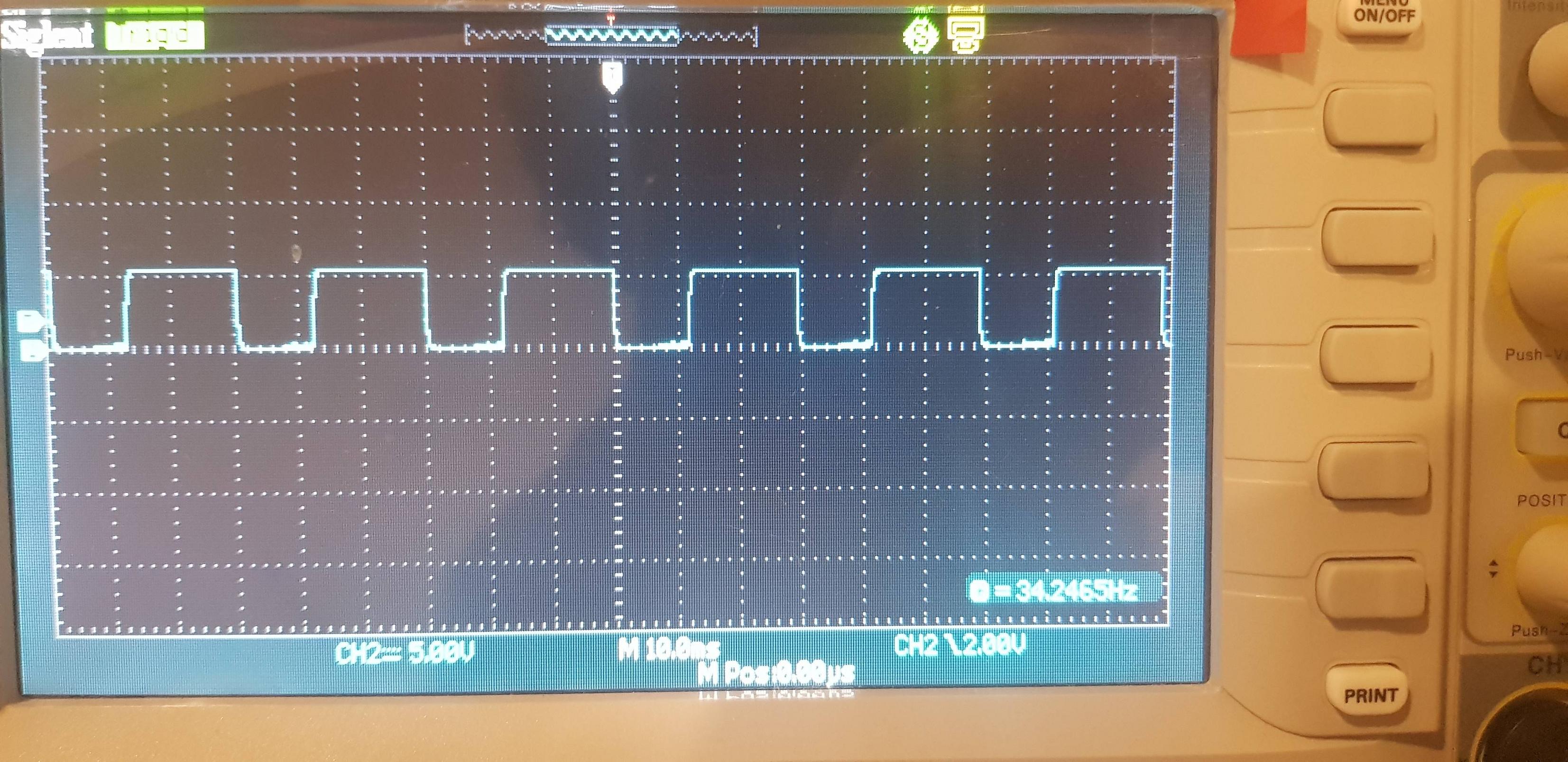
This is the PWM: Nice square wave

This is the circuit I've made: Circuit used

I have used 2 different MOSFETS and both give the same result.

What is causing the issue and what can I do to produce a nice clean square wave from the MOSFET?

Any help would be greatly appreciated.

\$\endgroup\$
9
  • 5
    \$\begingroup\$ What exactly is the nature of the load during this test? I presume that that unmarked capacitor on the drain in your schematic is not present? \$\endgroup\$ Commented Apr 29, 2021 at 13:28
  • 1
    \$\begingroup\$ Why the 1:2 voltage divider and capacitor on the gate? It slows down transition time and does not turn on the MOSFET as hard as it could be. How is the capacitor in series with the load supposed to be discharged each cycle? \$\endgroup\$ Commented Apr 29, 2021 at 13:34
  • 1
    \$\begingroup\$ Maybe you should favor us with a photo of your setup. You should have a capacitor across the 12V supply near the 555 (eg. 100uF). The 10n capacitor won't do anything good there, it should eliminate everything across the load after the first pulse. \$\endgroup\$ Commented Apr 29, 2021 at 13:38
  • 2
    \$\begingroup\$ Friendly reminder that trying to use a 555 in a HV power supply sounds like a recipe for pain. You'll find that every, even the cheapest, microcontroller excels very much as PWM controller, and that many modern microcontrollers are basically "power supply and motor control ASICs with a bit of programmable controller" more than anything else – this isn't a job for a 555, but for a microcontroller, IMHO. \$\endgroup\$ Commented Apr 29, 2021 at 13:43
  • 1
    \$\begingroup\$ Why not use a dedicated IC? They will outperform uCs. That 100n cap in the gate doesn't seem to be a sensible choice for speed. \$\endgroup\$ Commented Apr 29, 2021 at 14:10

1 Answer 1

1
\$\begingroup\$

I would strongly suggest you use a MOSFET driver like the MIC4416/17. Regardless of the nature of the PWM signal, whether is from a 555 timer or an MCU, a driver will level the signal up to the right Gate voltage (and buffer it for the adequate current, which for FET devices is irrelevant) to effectively turning on the transistor.

enter image description here

As others have pointed out, remove both capacitors from the gate and the drain, and if your load happens to be inductive, do NOT forget to add a snubber circuit and/or a flyback diode. For testing purposes, you can simply use a resistive load.

\$\endgroup\$

Your Answer

By clicking “Post Your Answer”, you agree to our terms of service and acknowledge you have read our privacy policy.

Not the answer you're looking for? Browse other questions tagged or ask your own question.