6
\$\begingroup\$

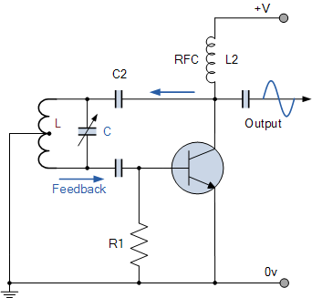
I've been playing around with fundamental circuits (no professional EE background), and became interested in oscillators. I have been trying to build the Hartley oscillator as described here. The document states that "an Hartley Oscillator circuit can be made from [...] a pair of series connected coils [...]".

I had a couple of 22mH fixed inductors, which I hooked up on a breadboard with the other needed pieces. When I test the transistor amplifier independently, it seems to be working. However, there is no sign of oscillation in this circuit.

So my ignorant question is, can I use the fixed inductors indicated? I saw mention of the notion of 'mutual inductance', and I'm not sure you can get such with these discrete components.

Update

My friends and I started out by copying Oli's quick circuit, and were gratified to get a crisp sinusoid waveform. Thanks, Oli!

However, I clearly still have a long way to go, as when we attempted to change the frequency of the circuit we were mimicking, we got zero oscillation. And the original Hartley circuit remains stubborn.

I've bought a couple of used books and will be working through them with an eye to getting the original circuit (among others) working.

\$\endgroup\$
2
  • 1
    \$\begingroup\$ I built a Colpitts oscillator the other day because it doesn't require the coupled inductors. en.m.wikipedia.org/wiki/Colpitts_oscillator \$\endgroup\$
    – jippie
    Commented Jan 29, 2013 at 20:28
  • \$\begingroup\$ Yep, that's on my list as well. Bear in mind that I'm doing this for education, so skipping the 'hard' one is counter to the spirit of the endeavor. ;^)~ \$\endgroup\$ Commented Jan 29, 2013 at 20:46

2 Answers 2

6
\$\begingroup\$

Although it's often shown as one inductor with a tap taken off somehwere, you can use two separate inductors for a Hartley oscillator.
You might want to consider capacitively coupling the feedback as in the second example, this will probably make it easier for your circuit to start to oscillate:

Hartley

You don't have to use the RFC choke shown, you can still use a resistor at the collector.

EDIT

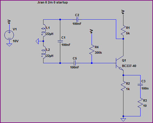
Here is my rough circuit with pictures and scope capture:

Hartley Circuit

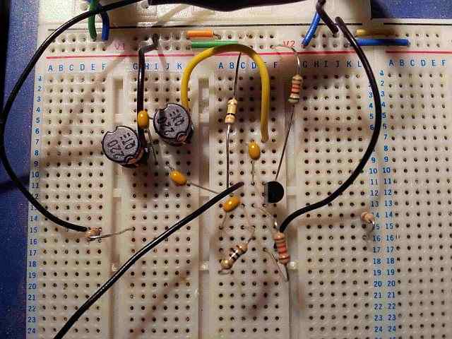
Picture on breadboard:

Hartley Pic

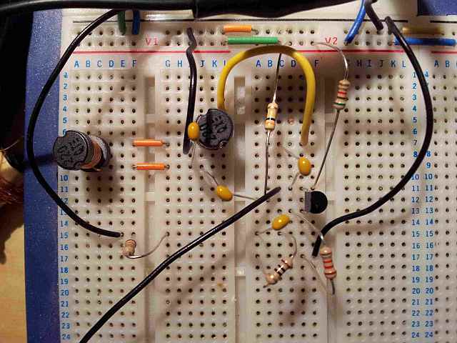
Just in case someone suggest coupling is taking place ;-)

Hartley Pic2

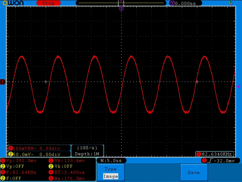
Scope Capture from collector (supply around 6V)

Hartley Wave

\$\endgroup\$
8
  • \$\begingroup\$ Are you implying L(top half) and L(lower half) do not need magnetic coupling? Just to make sure, I am not referring to L2 at all. \$\endgroup\$
    – jippie
    Commented Jan 29, 2013 at 21:03
  • 2
    \$\begingroup\$ Yes, they don't need coupling for the circuit to oscillate (but they can be coupled also) The equations are different in each case, see the OP's link. There are all sorts of variations with this type of oscillator. \$\endgroup\$
    – Oli Glaser
    Commented Jan 29, 2013 at 21:38
  • 1
    \$\begingroup\$ I think you are right, according to the formula there \$f_o=\frac{1}{2 \pi \sqrt{(L_{XY}+L_{YZ}+2M)C}}\$ varies with M (\$M = k \cdot \sqrt{L_{XY} \cdot L_{YZ}}\$, with \$0<k<1\$), but M can be 0. \$\endgroup\$
    – jippie
    Commented Jan 29, 2013 at 22:00
  • 2
    \$\begingroup\$ Just as a sanity check I built a quick non-coupled one on a breadboard and it oscillates (badly, as I haven't done any calculations, but it does oscillate - will post pics/circuit if anyone wants to see) \$\endgroup\$
    – Oli Glaser
    Commented Jan 29, 2013 at 22:13
  • 2
    \$\begingroup\$ Right, I added the circuit with a few pictures - as you can see, the output amplitude is quite small, but not too bad a sine wave. Note I capacitively coupled the feedback from collector as mentioned. It's not so easy to simulate (but it does) and the frequency agrees within a few kHz. \$\endgroup\$
    – Oli Glaser
    Commented Jan 29, 2013 at 22:47
2
\$\begingroup\$

According to the page you linked,

The feedback of the tuned tank circuit is taken from the centre tap of the inductor coil or even two separate coils in series which are in parallel with a variable capacitor, C as shown.

In this case "coil" is just a synonym for "inductor".

Note, though, that the circuit does depend on magnetic coupling between the coils. You won't want to use "shielded" inductors for this, and you may need to experiment with the physical arrangement of your two separate inductors to get it to work.

\$\endgroup\$
2
  • \$\begingroup\$ Thanks. I'd assume you would want them as close to each other as you can arrange to maximize the chances of coupling. Since they are in series, I've got them sharing one row on the breadboard (one pin each), so they're touching. Would you suggest that they actually be separated further? \$\endgroup\$ Commented Jan 29, 2013 at 18:16
  • 1
    \$\begingroup\$ Probably close and oriented parallel to each other. I'm not sure if end-to-end or side-by-side will work better. Also have a look at the linked questions on the right of the page --- there was a recent post with an example of doing this with air-core coils. \$\endgroup\$
    – The Photon
    Commented Jan 29, 2013 at 18:19

Your Answer

By clicking “Post Your Answer”, you agree to our terms of service and acknowledge you have read our privacy policy.

Not the answer you're looking for? Browse other questions tagged or ask your own question.