16
\$\begingroup\$

I am no expert in audio equipment, but to educate myself I have been studying. In the process, I came across a video which tests the audio frequency shielding of a purported shielded video cable. (I cannot attest to the fact that it is indeed a video cable, and I hope that I am not going down a rabbit hole). Anyway, the shielding was not very effective at audio frequencies. (Throughout, I am referring to shielding from electric fields, not magnetic.)

At first, this made sense to me. I reasoned as follows. The shielding is too thin. At video frequencies, the skin depth is very small, so a thin foil might still be several skin depths deep. However, at lower frequencies, that same foil might be less than a skin depth deep. Skin depth is known to be a factor in the effectiveness of shielding. Case closed. Or is it?

Upon further consideration, I am unsatisfied that the thinness of the foil in relationship to skin depth can explain why a video cable's shielding might be inadequate for audio.

Surely we can shield against DC without a foil as thick as N number of DC-skin-depths! Even at 60 Hz, the skin depth of (probably) aluminum, is much too thick for the effectiveness of shielding to depend upon skin depths. It is true that high frequency electric fields are exponentially attenuated when passing through a conductor, and this attenuation is related to the number of skin-depths of penetration. However, the skin depth for audio frequency electric fields is too large to account for the shielding effect of conductive foil. Rather, it is the low impedance pathway to ground that the foil provides that accounts for the shielding effect (at least as far as I can tell).

So, I next considered that perhaps the resistance of the foil is too high. But the length of cable used was small, and I don't believe it was driven with high current (though I can't attest to that). So I'm inclined to believe that foil resistance is not a significant factor here.

That leaves me mystified. Perhaps the video is not revealing important details or misrepresenting the facts. Perhaps there is a big gap in my understanding.

Is it true that a cable which is adequately shielded for MHz signals might be inadequately shielded for use as an audio cable?

If so, what is the mechanism that makes the shielding inadequate for audio frequencies?


Clarifications and concerns.

Regarding DC shielding. It is true that a DC electric field does not cause "noise". However, it is a well-known fact that in the electrostatic case, the electric field inside a cavity surrounded by a conductor is 0. That is, the electrons re-arrange themselves on the outer surface of the conductor to make the internal field zero. I have never heard, nor do I believe, that this effect requires a certain thickness of the conductor. So, shielding at DC, even though it is unimportant for preventing noise, illustrates, what I believe to be a fact, namely, that skin depth is not a factor for low frequency shielding.

Regarding the "inductive" pickup used in the video, I am quite sure it is not a magnetic pickup, but an electrostatic one. It appears to be similar to what is used in "fox and hound" tracing of wires through a wall. There are also do-it-yourself sensors that can be made with a FET and a short piece of wire (connected to the gate). These work by capacitative coupling to an electric field, not magnetic coupling.

Regarding the video maker allegedly failing to ground the shield. I considered this possibility, but given that the video maker knows at least a thing or two about audio, if he didn't ground the shield, it would have had to be intentionally deceptive. I also considered that possibility, but I just don't buy it. However, even if the video is a "fake" demonstration, the question still remains. Can a cable which is adequately shielded for video be inadequately shielded for audio? And if so, how does that work?

Regarding the use of unbraided wires as shielding, and consequently holes for EMI to pass through: First, I can't believe that such a cable would be useful at video frequencies. However, if it were, I would still wonder how it could have less shielding at audio frequencies. The electrical wavelength at audio frequencies is just too great. EMI passing through holes in a shield depends upon the wavelength of the EMI being less than the longest dimension of the hole. The cable itself is only a tiny fraction of an audio frequency electrical wavelength.

That brings me to magnetic fields vs. electric fields. At audio frequencies, the electrical wavelength is great. Therefore, we are almost certainly dealing with near field effects, rather than far field effects. In near field, the ratio between electric field and magnetic field is not governed by the nature of space itself (as it is in far-field), but by the nature of the transmitting antenna. Is the antenna mostly creating a (near field) electric field? Or a (near field) magnetic field? Again, by the nature of the pickup that the video maker was using, I think the lack of shielding that he was ostensibly detecting was primarily electric field in nature.

\$\endgroup\$
5
  • \$\begingroup\$ It doesn't at all appear that the second cable is shielded, and if it is, it is not clear the shield is connected to anything. Specifically a floating shield is not useful for anything! Moderate and low impedance inputs can tolerate more noise and less shielding. Shielding spec is an integral parameter of a cable specification. \$\endgroup\$
    – crasic
    Commented May 25, 2021 at 3:04
  • 5
    \$\begingroup\$ "Surely we can shield against DC without a foil as thick as N number of DC-skin-depths!" I don't understand what your point is here. DC doesn't induce anything so what are you trying to shield? \$\endgroup\$
    – DKNguyen
    Commented May 25, 2021 at 4:11
  • \$\begingroup\$ According to the product page (prepare for giggles: cardas.com/clear_sky_ic.php ), it is not a magnetically shielded cable. Nothing in that cable makes it better in shielding for audio than a normal braid shielded coax. Maybe just the thicker isolation makes the prope be further from the conductive parts. \$\endgroup\$
    – tobalt
    Commented May 25, 2021 at 8:46
  • \$\begingroup\$ not at all convinced by that video demo. What he is hearing is very likely HF pickup that has an audio component, you hear the audio component (because that's all you can hear) but the actual pickup signal is well into RF range. \$\endgroup\$
    – danmcb
    Commented May 25, 2021 at 9:09
  • \$\begingroup\$ Thanks for the link about the "JFET electrometer". These can detect tiny potential wobbling. I guess two things come together here: 1) at the black cable, he probes closer to the current path (which goes from core to shield) 2) the blue cable shield is closer to ground. naturally the potential at the far cable end will wiggle a bit more, this is increased when the braid is thin. So what about shielding? If you pass around such high impedance signals that are sensitive to this difference in shielding, the cable capacitance loading is your greater problem anyway. Tackle with preamplifier. \$\endgroup\$
    – tobalt
    Commented May 25, 2021 at 15:49

5 Answers 5

15
\$\begingroup\$

It is conceptually possible to induce magnetic interference at audio frequency in an electrically shielded cable, which is not so much possible at higher frequencies due to the shields becoming opaque for magnetic fields. You just can't ignore magnetic fields at audio frequencies. Normal conductors usually used for shields (aluminum/copper) will not shield them at all.

While you could use, e.g., mu-metal to shield cables electrically and magnetically, the tried and true (and cheaper) way to protect against magnetic field interference in audio is the same as in UTP cables: differential signaling, twisted cables and steel chassis.

Todd Hubing made a two video series that you can watch on YouTube:

It shows very nicely that all metals shield at high frequencies, but only the magnetic materials shield at low frequencies.

On a slightly separate note, I have my serious concerns about the scientific rigor of the linked YouTube video. The guy in the video sounds like he wants to sell expensive cables using mu-metal foil shields or something.

In fact, it is a sales video for this voodoo product. But the cable doesn't even have magnetic shielding, just some voodoo ingredients like air tubes and "clear sky conductors". I am not saying that the video is fake, but the whole demo is probably designed to "reveal" some purported advantage of these cables, which is inconsequential in real-life. For example, the blue cable could have a thicker insulation, so the noise probe can’t pick up near field effects as effectively. Or the black cable could have a disconnected shield at one end (I've seen such things), and its shield could be floating. Or the black cable could be just a cherry-picked bad example.

\$\endgroup\$
4
  • \$\begingroup\$ Why is that you can "ignore" the magnetic fields at higher frequencies? That never seemed to make sense to me since it's an electromagnetic wave. It always seemed strange to me that magnetic interference is treated separately from electrostatic interference since the two are both propagate each other as an electromagnetic wave. so it should be the same thing inducing noise either way. And yet, me spinning some magnets wire seems clearly different than a noisy wire or antenna inducing noise on that same signal wire. \$\endgroup\$
    – DKNguyen
    Commented May 25, 2021 at 6:52
  • 6
    \$\begingroup\$ @DKNguyen At higher frequencies, the Al/Cu shields are effective at blocking the magnetic component of the EM radiation due to eddy currents. Remember: Eddy currents form a magnetic field that opposes the magnetic field creating them -> they shield against magnetic fields. \$\endgroup\$
    – tobalt
    Commented May 25, 2021 at 6:55
  • \$\begingroup\$ Hmmmm. Interesting. I've never heard it put that way before. That gives me a good lead. So would that mean that using something like ferrite as a shield would be detrimental since nothing would be there to sap the magnetic components of their energy? \$\endgroup\$
    – DKNguyen
    Commented May 25, 2021 at 6:56
  • 1
    \$\begingroup\$ @DKNguyen "So would that mean that using something like ferrite as a shield would be detrimental since nothing would be there to sap the magnetic components of their energy?" Yes and No. Ferrites don't block by eddy currents as they don't conduct well, but they also retain their permeability up until very high frequencies. So they would make quite good magnetic shields I suppose. I think they aren't shapable as well as a sheet of mu-metal though. And a pure ferrite shield wouldnt provide good electric field screening. \$\endgroup\$
    – tobalt
    Commented May 25, 2021 at 10:39
7
\$\begingroup\$

There's no reason to think the shielding has a monotonic impedance. There are parasitic inductances and capacitances lurking in the cable so it would be expected that there are impedance peaks and valleys.

It could just be the cable designers bothered to make the impedance low at video frequencies and so audio frequencies fall into a region of high impedance. And that impedance vs. frequency curve would be dictated by everything about the cable including construction, materials and geometry.

My understanding is that it's always about low the impedance of your shield is relative to your signal path, including the skin effect and low impedance paths to ground. All the same thing concept. The noise (currents and electric field) collectively travel in a sort of loop with a return path, and it is similar to current traveling through parallel resistors. Some noise will go down each resistor but the proportion of noise that ends up down each path depends on the relative magnitude of the resistance (or technically impedance).

One resistor is represents the path provided by the shield, and the other represents that provided by your signal path. Your goal is make the impedance presented by your shield very low relative to the signal path and keep it that way. That way, the vast majority of noise currents will flow through your shield and very little in your signal path.

But here's the catch: noise, particularly high frequency noise can travel by capacitive coupling (which is pretty much the same mechanism physics-wise as the electric fields inducing noise in the first place). I'm tempted to say that signal transmission between two antennas is almost like electromagnetic energy transferred between to plates of a capacitor.

So even if you insulate your signal path, the noise can still capacitively couple through that insulation to get into your signal path. Essentially forming an antenna, even if you isolate things so the electromagnetic energy leaves the conductor and travels through the air (via capacitive coupling) to its destination. Even if you surround your signal path in a shield to intercept the electric fields, so they cannot directly induced noise in your signal path, there's no guarantee that the noise now induced in the shield won't capacitively couple to your signal path and induce noise there, essentially jumping from your shield to the signal path.

A given capacitance presents a higher impedance for a lower frequency, so low frequency noise can't capacitively couple from the shield to the signal path so easily. In other words, the shield itself tends to present a much lower impedance path to flow in a loop than the path that involves the signal path with a shield-signal path capacitive coupling in the way.

But this is not the case for high frequency noise. In high frequency noise, the capacitance between shield and wire might be low enough impedance that the route involving the signal path is lower than the one down the shield (the shield has inductance just like a wire). That's when you get noise in your signal path even though you have a shield. Things like holes (or apertures) in your shield not only provide a way for the electric fields to get past your shield and directly induce noise on your signal path, but it allows noise currents in your shield to travel from the outside of the shield to the inside of the shield where they can then capacitively couple into the signal path.

And all the skin effect is, is a mechanism that you can take advantage of to fight against how easily high frequency signals can capacitively couple from the shield to the signal path. The skin effect provides a way for you to present a high impedance in the middle of that otherwise low impedance path between outside of the shield and signal path within (and apertures bypass this as mentioned in the above paragraph).

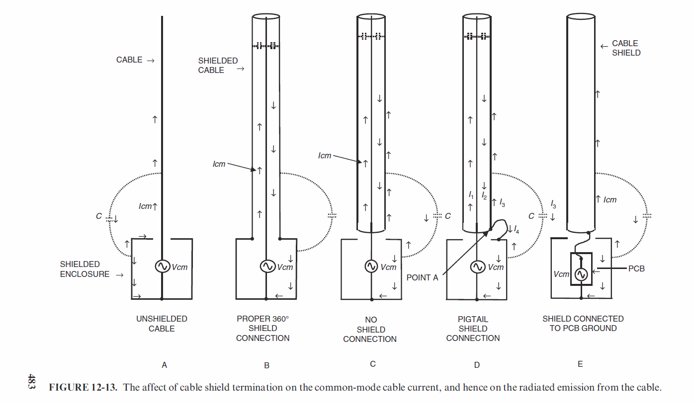
That's also why you need a circumferential connection between your shield layer and the outside of your enclosure. If you use a wire to connect your cable shield to your enclosure, that presents a high impedance path between the shield and noise. From there, the noise currents on the outside of the shield will try to find an easier route and can travel around the end of the shield to the inside where there's a large capacitive coupling between inner shield and signal wire. And if you don't ground the shield, the noise currents will find a way by capacitively coupling to everything around which is probably going to include your signal wire as well as through the air to your enclosure.

Enter image description here

Note the capacitive coupling through the air, as well as the currents travelling on the outside of the shield around the edge of the shield to the inside of the shield. Taken from Electromagnetic Compatibility by Henry Ott.

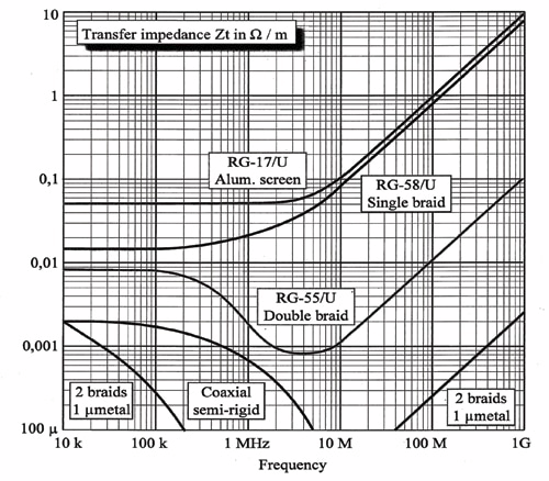
Check these curves and explanations for different shield constructions: How to Select Cable Shielding for Electromagnetic Compatibility – Part 3

Also, for interest:

Enter image description here

Simple Method for Predicting a Cable Shielding Factor, Based on Transfer Impedance

\$\endgroup\$
1
  • \$\begingroup\$ I think that your figure C is most likely what we have in the video. I don't see any magnetic coupling because the end of the cable is open and no current is flowing. And if no currents flow and magnetic coupling is not an issue, skin depth is not an issue. The probe is capacitively coupled, so it is electric fields we are dealing with. So your figure C is the most likely explanation. \$\endgroup\$ Commented May 30, 2021 at 0:48
5
\$\begingroup\$

From direct experience (adding shielding to a mixing desk which was modified to include a build in mains PSU), to shield magnetic signals (like mains transformers) at 50Hz and LF harmonics thereof, you need SIGNIFICANT mass of ferrous material. We actually bought mu-metal and did use it but the best turned out to be big chunks of pig iron scavenged from the workshop. It did get heavy though.

The primary mechanism of rejecting LF "hum" in audio systems is low impedance line drivers, and balanced circuits where the receivers have high CMR (especially in mic circuits). Shielding on audio cables is useful and important but what you are keeping out here is more RF which will contain audible components - clicks, buzzes etc.

\$\endgroup\$
2
  • 2
    \$\begingroup\$ Thank you for your first hand experience. Regarding the interference being RF, if you watch the video carefully, you see that he has reversed the roles of "attacker" and "victim". He is feeding an audio signal through the cable and picking up an electric field outside the cable. By the reciprocity principle, that means an electric field outside the cable could induce a noise signal in the cable. But the noise in this case is clearly audio frequency. \$\endgroup\$ Commented May 25, 2021 at 11:34
  • 2
    \$\begingroup\$ @MathKeepsMeBusy yes, my bad. I need to look again more closely. But somewhere I am still highly sceptical of what he is purporting to show here. \$\endgroup\$
    – danmcb
    Commented May 25, 2021 at 12:12
3
\$\begingroup\$

Thanks to @tobalt for pointing out that the other end of the cable is open. For the same results to apply when there is a receiver, the receiver has to have a high-z input (normal for audio) and there can't be a ground loop (maybe the transmitter is on battery). I will attempt to explain what happens in that case.

We can estimate the fields surrounding it as follows. Suppose the source is 1 kHz and 1V. The skin depth of copper at 1 kHz is about 2 mm, probably larger than the thickness of the shield. As an estimate, the cable has resistance of 100 mΩ, capacitance of 100 pF, and inductance of 250 nH. Its resistance is much larger than its inductive reactance, so it can be modeled as a capacitor in series with the resistance from one end to its middle. Current into it is \$\frac{V}{j \omega C}\$, about 1.5 μA. And current in the middle is half of that. The longitudinal electric field on the inside of the shield is that current multiplied by the resistance per unit length of the shield, about 100 nV/m. While the azimuthal magnetic field is that current divided by circumference, about 300 μA/m. Since the shield is thinner than skin depth, fields on its inside and outside are of the same orders of magnitude. We see that the ratio between electric field and magnetic field is much less than 377 Ω. Thus there is more inductive interference than capacitive.

At 1 MHz, the skin depth of copper is 20 μm. Current is 1000 times as high now. A solid shield 7 times the skin depth thick dampens the fields by 1000 times. So that cable may produce more interference at audio frequencies if the cable is unterminated even for video. If the receiver end is terminated when transmitting video, the current will be much higher, and thus more inductive interference will be produced.

Ways to get less interference, and why the cable the guy is selling seemed better in the video:

  • Take the probe farther away from the center of the cable. Because the magnetic field is inversely proportional to circumference. Using a thicker cable does this.

  • Use a cable that has less capacitance. Most effectively accomplished with a shorter cable. Otherwise the cable can be made to have a small capacitance per length, which means a larger shield and thinner center conductor, which changes its characteristic impedance and makes it unsuitable for high frequencies.

  • Use a shield several skin depths thick. Which is about 2 mm of copper or 20 μm of permalloy at 1kHz. At 1 MHz, the skin depth of copper is 20 μm, so the cheap cable's shield is effective.

I originally thought the setup was the cable connecting a transmitter and receiver both terminated with 75 Ω. What would happen is explained below.

In summary. At low frequencies current follows the path of least resistance (the ground loop). At high frequencies current follows the path of least inductance (the signal cable). Ground loop affects unbalanced signals more at low frequencies.

Suppose a signal source is placed between the center pin and ground at the output connector of one instrument via a 75 Ω resistor. The current has two paths to flow down. Remember that current always flows in a loop, and the return path is simply half of the loop labeled as such.

  • Center conductor of the bad cable, 75 Ω input impedance of the receiver, shield of the bad cable.

  • Center conductor of the bad cable, input impedance of the receiver, chassis of the receiver, ground wire of its power cord, ground wire of transmitter's power cord, transmitter's chassis.

The ratio of currents in these two paths is the inverse of that of the impedances not shared by both paths. For the first, it is the wire's resistance, on the order of 100 mΩ. For the second, it is the inductance of the ground loop on the order of 1 μH, plus its resistance which should be less than that of the cheap cable's shield because power wires are usually thicker.

Thus for audio frequencies, the impedance of the ground loop is smaller, and a significant portion of the signal current flows in it. Because the ground loop is much larger than the signal pair loop, it emits much more inductive interference.

For video frequencies, we can see that the inductance of the ground loop is significantly larger the resistance of the signal pair. Thus less current flows in it. So less inductive interference is generated. And yes, at about 1 MHz a loop of about 1 m across is still much smaller than the wavelength, so we can still analyze it as a lumped circuit and it still emits more inductive interference than capacitive.

And thanks to reciprocity, the more interference something emits as an aggressor, the more it picks it up as a victim.

For the shield to be effective at low frequencies, its resistance needs to be at most comparable with the inductance of the ground loop. This requirement is roughly the same as requiring the shield to be as thick as the skin depth.

To answer your questions directly. It is true that a cable which is adequately shielded for MHz signals might be inadequately shielded for audio. It is because the shield may not be thick enough. There is no electric field inside a cavity surrounded by a perfect conductor. When the conductor has resistivity, current flowing through it produces an electric field as dictated by Ohm's law. In a perfect conductor, skin depth is always 0. That is why superconductors only need to be a film over a non-superconducting substrate.

\$\endgroup\$
4
  • \$\begingroup\$ There is no 75 Ohm termination in the video. Neither is there a chassis to provide Earth return. Also noone in audio would load a signal source with a 75 Ohm load as that would produce quite the harmonic distortion. Also why does the return current path matter for shielding ? \$\endgroup\$
    – tobalt
    Commented May 25, 2021 at 10:30
  • \$\begingroup\$ @tobalt How do you know there is no termination? I don't find him mentioning it in the video, and usually these instruments have matched outputs and inputs. Although analog audio lines are usually not terminated, I thought I would stick to the example in the video in which I thought both ends were terminated. Anyway, the analysis still applies if the load is changed from 75 Ω to a small capacitance. As for why the return path matters, I have edited my answer to make it more clear. \$\endgroup\$ Commented May 25, 2021 at 13:53
  • \$\begingroup\$ At 0:55 in the video you can see that he disconnects the black cable and then attaches one end to the blue cable, leaving the other one open. So there is no GND return path through another chassis. The only ground return path for both cables is through the cable capacitance. \$\endgroup\$
    – tobalt
    Commented May 25, 2021 at 13:57
  • \$\begingroup\$ @tobalt I hadn't noticed that he had disconnected the other end. I will have to look more into it. \$\endgroup\$ Commented May 25, 2021 at 14:06
2
\$\begingroup\$

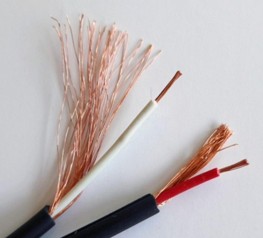
The cheap cable in the video is constructed like this:

enter image description here

There is an insulated wire in the center, loosely wrapped with "shield" copper threads. Since these are not braided, and there is no foil, there are a lot of holes in the "shield". Also copper costs money, so the number of threads is in proportion to the price. Cheaper cable have less shield threads, thus higher shield resistance, and more holes.

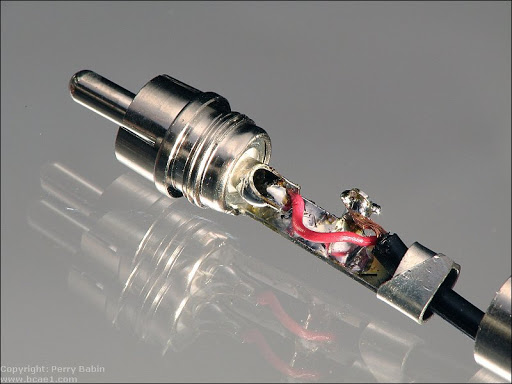
The connectors are also cheap and they do not make a coaxial connection: inside the connector's plastic shell, the center conductor is unshielded.

enter image description here

These cheap cables and connectors don't have well controlled impedance, so they're not recommended for HF or video (or anything else really).

Surely we can shield against DC without a foil as thick as N number of DC-skin-depths!

DC emits no magnetic field, so this would be electrostatic shielding. Any foil would work.

Even at 60Hz

At high frequency, the mechanism behind shielding is simply reflection. It works like a mirror, which is a conductive metal film deposited on glass, or a parabolic dish, which is a piece of (conductive) metal. To simplify, an incoming electromagnetic wave induces a current in the conductor, and this current creates another reflected electromagnetic wave that cancels the incoming one. This second wave then goes off propagating in free space and we call it "reflection". Behind the shield (or the mirror) the two fields cancel.

However induction works proportional to frequency, so at low frequency there isn't much of it, and the shield is not effective.

To shield against low frequency magnetic fields, you need a different mechanism, for example a ferromagnetic material that will direct the field where you want it, for example a steel enclosure. This is not practical for cables, which is why professional audio uses balanced (differential) twisted pair interconnects: both conductors pick up the same amount of noise, the receiver does a subtraction and cancels it.

However, I think what he's showing in the video is some different effect. It's weird that the magnetic pickup detects anything, since the cable is unterminated, with no load at the end, there should be very little current flowing in it, hence very little magnetic field to detect. I think the probe is also detecting electric field from the cable. It makes sense the cheap cable would emit a lot more of it due to its low quality shield (lots of holes) and crummy connectors which will do some differential to single ended conversion.

Another issue with the cheap cable is copper costs money, so there's not much of it, and the shield has high resistance. With unbalanced connections, any current flowing in the shield ("ground loop") becomes part of the signal when converted into a voltage by the shield impedance. So the higher that is, the more noise. This is not an issue at HF simply because the receiver is usually AC coupled and acts like a high pass filter, so it doesn't care about 50Hz and other low frequencies.

\$\endgroup\$
4
  • 3
    \$\begingroup\$ The "holes" in a braid shield are less than a mm in size.. I doubt audio wave length electric fields will slip through at many km of wavelength. Even in the cheapest of china cables. I was also wondering why he picks up stuff on one cable but not the other.. but then I decided not to bother given the general fishiness of the video. \$\endgroup\$
    – tobalt
    Commented May 25, 2021 at 8:34
  • 2
    \$\begingroup\$ rofl, I found the product web page of the cable. Read the construction part :D cardas.com/clear_sky_ic.php "Cardas Copper", "Non-conductive air-tube", "Clear sky conductors", "Matched propagation"... and more. This is total "audiophile" voodoo \$\endgroup\$
    – tobalt
    Commented May 25, 2021 at 8:42
  • \$\begingroup\$ The amount of holes depends on how much it was "cost-optimized", sometimes I've cut some of these cables to make a pigtail and found so little copper it was ridiculous. If this was a "measurement" video not a "buy my product" video, he'd do the measurement again with the cables swapped. Agree on the snake oil overload. \$\endgroup\$
    – bobflux
    Commented May 25, 2021 at 8:44
  • \$\begingroup\$ Right, maybe he selected a particularly crappy cable with very uneven and leaky shield \$\endgroup\$
    – tobalt
    Commented May 25, 2021 at 8:54

Your Answer

By clicking “Post Your Answer”, you agree to our terms of service and acknowledge you have read our privacy policy.

Not the answer you're looking for? Browse other questions tagged or ask your own question.