1
\$\begingroup\$

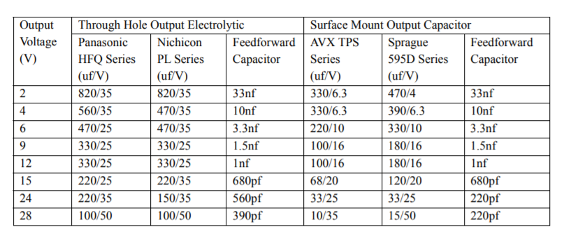
I am relatively new to electronics and trying to design a buck converter circuit using the XL1509-ADJE1. The datasheet specifies that for the adjustable versions (which this is) you should use specific capacitor values depending on the output voltage you desire. The only issue is, I need 3.3v out and the datasheet only gives capacitor values for 2v and 4v (and upwards). What value should I use?

Another weird thing I wanted to know (just out of interest) is why the datasheet gives different capacitance values depending on the type/brand of the capacitor. I have included the table from the datasheet and as you can see it shows different values for electrolytic and tantalum capacitors. enter image description here Thanks! :)
\$\endgroup\$
0

2 Answers 2

3
\$\begingroup\$

The output capacitor affects ripple and transient response so it doesn't need to be too exact. Larger = less ripple but slower response. The feedforward capacitor is the one I would be more worried about. I suppose you could just plot out the output voltage vs feedforward capacitor and interpolate the curve.

The capacitances for tantalum and electrolytic are different because the capacitors have different frequency characteristics such as ESR, impedance at your target frequency, and bulk capacitance.

For example, if your primary aim for a particular ESR one type of capacitor might be able to achieve that at a lower capacitance than another type.

If your primary aim is to achieve a particular impedance at a particular frequency, that again would result in different capacitance between capacitors of different types.

\$\endgroup\$
8
  • \$\begingroup\$ So if I use a ceramic capacitor instead of tantalum or electrolytic for the output capacitor, what value do you reccomend I should use \$\endgroup\$
    – beans
    Commented May 26, 2021 at 17:48
  • \$\begingroup\$ Just follow the table you posted. \$\endgroup\$
    – DKNguyen
    Commented May 26, 2021 at 17:48
  • \$\begingroup\$ it doesn't give values for ceramic, and the answer below yours says something about using a third to a tenth of the electrolytic value. do you agree with that? \$\endgroup\$
    – beans
    Commented May 26, 2021 at 17:55
  • \$\begingroup\$ @ArduinoBobby That's because ceramic capacitors don't come in values that large (i.e. there is often a minimum target ESR and minimum capacitance that have to be met and ceramic doesn't meet the capacitance requirement even if it is very low ESR). \$\endgroup\$
    – DKNguyen
    Commented May 26, 2021 at 18:47
  • \$\begingroup\$ You'd be hard pressed finding a ceramic capacitor above 10uF. At least, of any of the good dieelectrics like X5R. X8R, or X7R that only vary +/-15% rather than something ridiculous like +/-80% over temperature. Ceramic cap dielectrics other than C0G/NP0 also suffer from DC bias (the more DC bias you apply across them, the lower the effective capacitance (20% if I remember at their max rated voltage). Electrlytics (and I think tants) do not. \$\endgroup\$
    – DKNguyen
    Commented May 26, 2021 at 18:51
1
\$\begingroup\$

There is no easy answer to why different capacitors stabalize different circuits. But as far as power supplies and SMPS are concerned. The primary metrics of concern are equivalent series resistance, voltage / dielectric stability and finally frequency response. You can use much lower value ceramic capacitors due to their relative frequency stability compared to electrolytic. Not to mention electrolyte based capacitors deteriorate with temperature and time and need to be over specified. Tanatalum capacitors in particular have very favorable ESR characteristics, this is to say their own internal resistance is so low they absorb current relative to time so quickly that for a brief period of time they can perform some tasks normally performed by a resistor in series with the capacitor namely receiving or reducing inductive spikes. There for they have generally an equivalent series resistance.

I recommend using a ceramic capacitor, depending on application you can generally use a ceramic capacitor 1/3rd to 1/10th the required electrolytic value. Or a relatively high ESR tantalum. You generally want LOW ESR input capacitors and most of the time the output can also be LOW ESR. But a low ESR on the output can cause tracking and regulation issues in certain cases.

The best over all general purpose capacitor type is a ceramic they don't light on fire very often and are incredibly reliable as they have no liquid electrolyte and their frequency stability is superior.

\$\endgroup\$

Your Answer

By clicking “Post Your Answer”, you agree to our terms of service and acknowledge you have read our privacy policy.

Not the answer you're looking for? Browse other questions tagged or ask your own question.