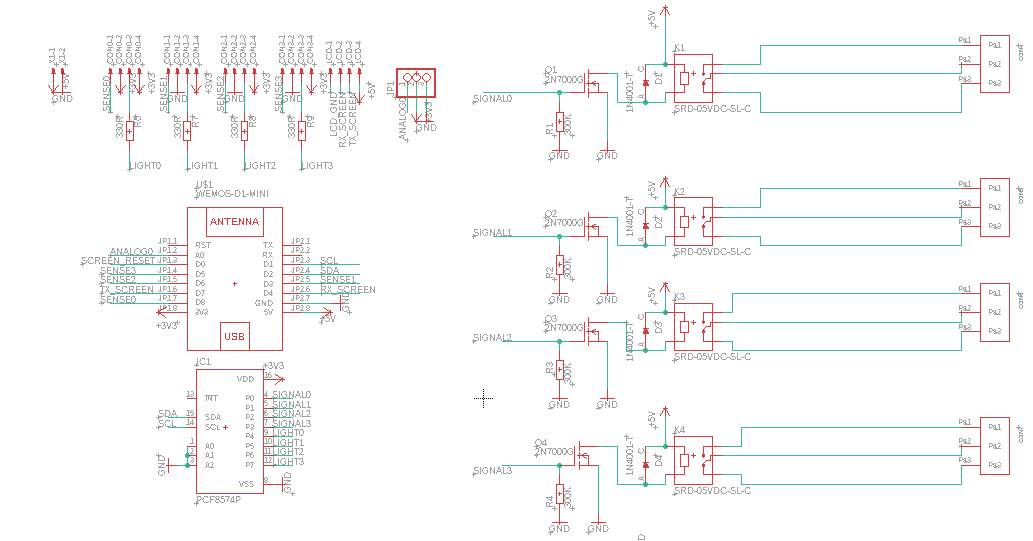
Recently I designed a board to control the lights in my home remotely via HomeAssistant (ESPHome using a WeMos D1 Mini). Due to the lack of pins, I am using a PCF8574 to actuate the relays. The main issue I am facing is that when switching off fluorescent lights (be in PL-C 2 pin or tubular), the entire circuit (all the relays on the board) glitches to "ON".
Here is a circuit diagram of my board:
 As requested the .pdf files for the board and schematic.
A video of the problem I am facing can be found here. Between 0:00-0:27 of the video, I cycle through all LED lights in the room (using the remote app) and they work fine. at 0:27, I turn on the problematic fluorescent light. At 0:31, I attempt to turn it off but it doesn't turn off and causes all the lights in the room to suddenly turn on. Checking the logs shows that the ESP8266 did not reset nor did any of the PCF8574 pins go to "HIGH" during the period of the malfunction.
Hence I likely suspect that this issue is caused either by the PCF8754 glitching out or perhaps caused by some form of interference caused by the circuit design.
Interestingly, I had tried the board out before installing it on similar PL-C 2 pin bulbs which can be found here. As such, it's really perplexing as to why the circuit would have failed when being installed.
Currently, I have the following hypotheses (in order of likelihood:
The PCF8574 glitches out when fluorescent lights are switched off on the relay. The cause behind this is unknown as I lack a proper oscilloscope and the know-how to troubleshoot the PCF8574. Solution: Redesign the board and switch the relay pins to the ESP8266 and leave the PCF8574 to do the sensing on the button and the outputs on the light
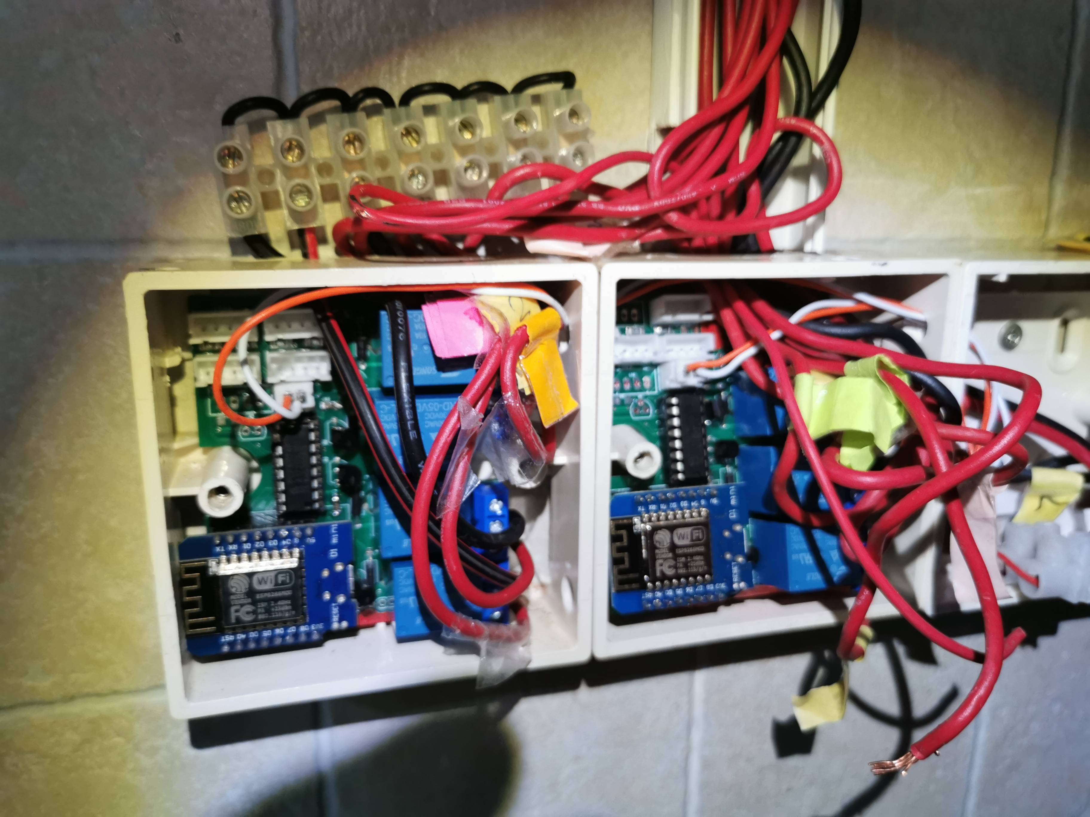
Magnetic interference caused by the tangled nature of the wires could be causing the PCF8574 to glitch out. For reference, here is an image of the board being installed in the switch box:
 Solution: Better wire management (which has been done, greatly reducing the amount of wire clutter); possibly isolating the wires from the circuit board using an aluminium foil?
Lack of isolation between load circuit and signal circuit. Solution: Redesign the board with optocouplers to switch the relay with a separate power supply for the relays and the IC components.
I have written about this in greater detail in my blog here and have linked the relevant eagle files here if it is helpful.
As I am still a beginner when it comes to circuit design, I would be greatly appreciative of anyone who could point me in the right direction! Thanks everyone in advance!
