3
\$\begingroup\$

I'm building the Arduino spaceship interface from the project book and everything works fine. It involved connecting 3 Arduino outputs to 3 leds, and 1 Arduino input to the a switch. For a photo of the setup, please see here: http://imm.io/V5oh
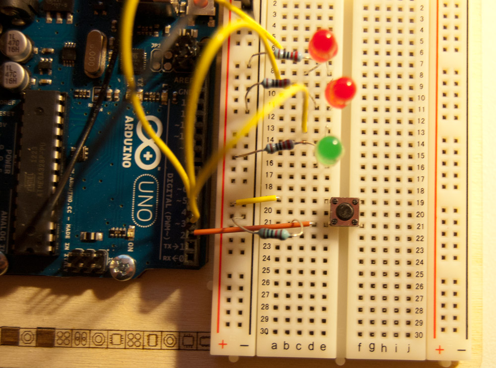

(source: i.imm.io)

The switch is set up like this: 5V ---- push button-----10kOhms------0V

The Arduino input is connected between the push button and the 10kOhm resistor.

My question is: Why is the 10kOhm resistor needed? The manual says it is needed so that the Arduino "reads LOW when there is now voltage coming in through the switch".

Could I not simply get rid of the resistor completely (just replace it with a wire), then if the switch is open, it will still be connected to the ground and still read LOW? What is the resistor actually doing, if anything?

\$\endgroup\$
2
  • \$\begingroup\$ electronics.stackexchange.com/questions/11112/… \$\endgroup\$
    – pjc50
    Commented Feb 3, 2013 at 21:41
  • 1
    \$\begingroup\$ note that the AVR microcontroller has internal pullup resistors that you can enable. so you can connect the button between input and 0V and save one external component. however, you must change the software so that a low level input is recognized as a button press. \$\endgroup\$ Commented Feb 14, 2013 at 16:43

2 Answers 2

3
\$\begingroup\$

Without the resistor, if you press a button, you'll short 5V to 0V and BAD THINGS will happen.

On another hand, if we leave bad things for a moment as a thought experiment, what level would arduino read?

5V ----+---- 0V

The voltage at the + would be defined by the ratio of resistances of wires going from 5V and 0V to a + point. This would be tricky to set up properly, so it's better to put a big resistor (much bigger than wire resistance) and have the result predictable.


Edit

by BAD THINGS I mean - what does happen when you short a battery? In theory unlimited current flows from positive terminal to negative, in reality this current is limited by internal resistance of the battery, battery heats up, potentially explodes or leaks. If you are powering from USB - usb circuitry inside computer fries (this rarely happens as computers usually have protection circuitry). If you are powering circuit from a wall-wart adapter, a fuse in it might blow or it can catch a fire if it's of some extremely crappy chinese origin. If your power supply is strong and robust enough (like lead acid battery or lithium cell), a power trace on a PCB can burn off. In this particular case nothing bad would happen - arduino has a resettable PTC fuse on board, it will just reboot.

\$\endgroup\$
2
  • \$\begingroup\$ Thanks for this, great explaination. Could you say what the bad things are? I thought something bad might happen if I removed the resistor which is why I originally asked, saved me from experimenting and wrecking something! ;) \$\endgroup\$
    – Lars
    Commented Feb 3, 2013 at 22:12
  • 1
    \$\begingroup\$ I guess we need a PULL-UP AND PULL-DOWN RESISTOR MANNUAL!! \$\endgroup\$
    – sheetansh
    Commented Feb 14, 2013 at 11:12
0
\$\begingroup\$

The correct way to wire things is this: Pin-button-Gnd. No 5V involvement.

In the code:

byte button= 2;
byte buttonState;

void setup(){
pinMode (button, INPUT_PULLUP);
}

void loop(){
  if (digitalRead(button) == LOW){
  // button is pressed, do something
  }

// or
  buttonState = digitalRead (button);
  if (buttonState == 0){
  // button was pressed, do something
  }
}

That uses the internal pullup resistor, no external components needed, and takes away any chance of shorting 5V to Gnd and damaging the 5V regulator, or blowing the USB fuse, etc.

\$\endgroup\$

Your Answer

By clicking “Post Your Answer”, you agree to our terms of service and acknowledge you have read our privacy policy.

Not the answer you're looking for? Browse other questions tagged or ask your own question.