I'm an extreme newbie when it comes to electronics, and decided to just dive right in.
I wired up my buck converter exactly like how it's done here: https://www.youtube.com/watch?v=fmdxSRaVPVg
Without a load, everything works fine. I was able to use the trimmer to set a max output of 6V, and the potentiometer (10k) allows me to vary output voltages from practically 0 to 6V. I'm using a 12V 2A DC wallwart as my input.
Now, I have some cheap fairy lights (The ones that are basically just parallel LEDs.) When I got them they were powered by 2x CR2302 batteries (in series.)
I was thinking everything would work out if I just connected my now liberated fairylight string to the output of the buck converter, as it's now outputing a clean 6V.
When I connect the fairylights to the converter, the lights will blink non-stop, and my buck converter stops displaying anything on it's built-in voltmeter. If I dial the potentiometer all the way down, I get a blinking red light on the buck converter for the 'IN'. The same issue occurs even when the potentiometer is removed.
Any ideas what's causing this and how to fix it?
MORE INFO:
- I haven't had much luck finding the exact model of the buck converter, since whenever I find it, it's only labeled as 'LM2596ADJ'
However, I do know the following specs:
- Input Voltage 4.5~ 40V.
- Output Voltage range 1.25V ~ 37V
- Output Current max 3.0A (recommended 2.0A)
- For the fairylights themselves, I really have no idea, but after using the multimeter, whenever I try to measure the current, it jumps around from 100mA to around 50mA.
EDIT, unfortunately, I don't know how to make schematics/diagrams, so hopefully some embedded photos will do.
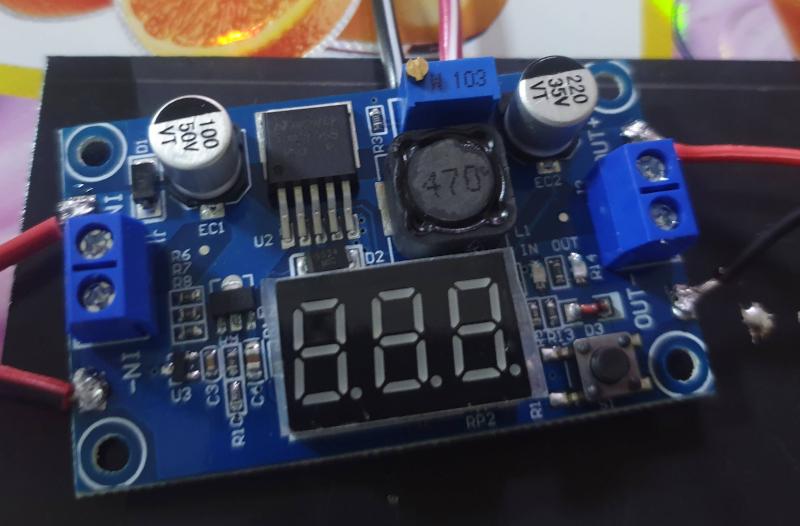
Here's the completed board. Don't mind the poor solder joints, please.
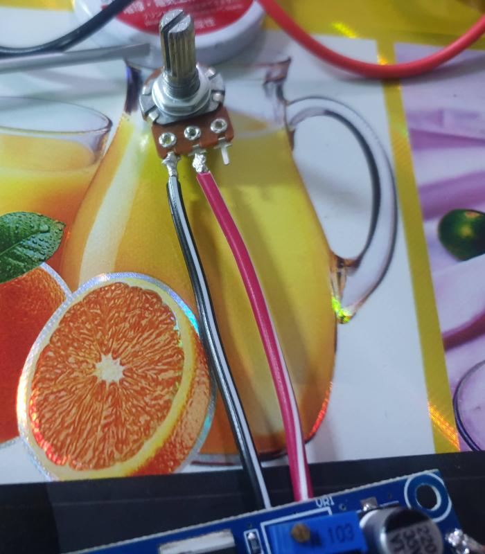
Here's the potentiometer at the top. It's 10k.
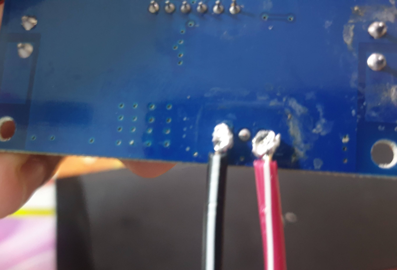
How the pot-meter is joined to the board:
Here are some images/videos of what I've done: https://i.sstatic.net/7COEs.jpg


