0
\$\begingroup\$

I am using TPS5450 buck regulator and trying to measure the transient response but seem to see a weird triangular adjustment before it settles. I can't see anything in the datasheet that would explain this and my design is based on typical suggestions from webbench.

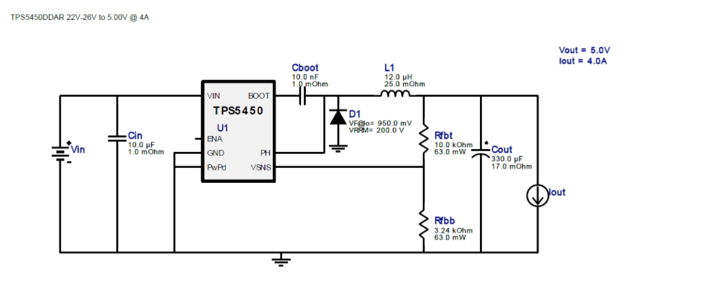
Here is my schematic: enter image description here

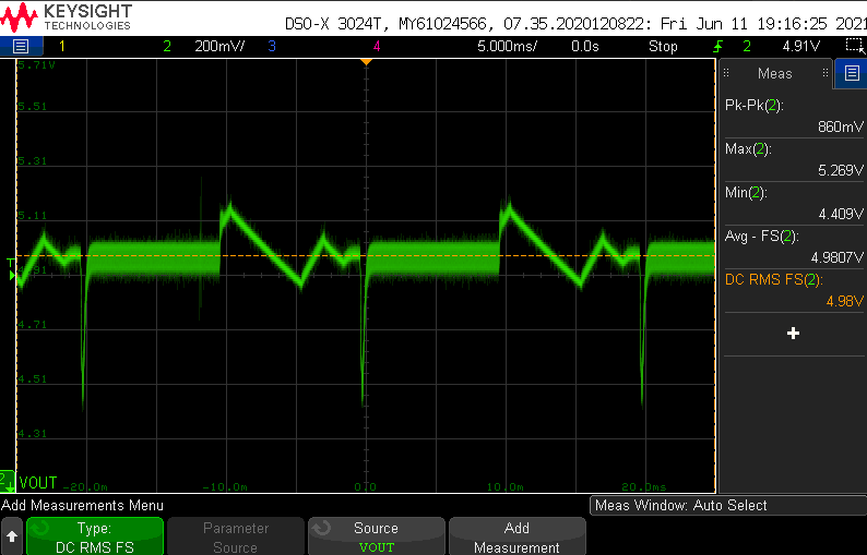
And this is the output response i see when i switch an electronic load between 1A and 0A with 50% duty cycle:

enter image description here

Interestingly, by adding an offset to the load (switching between 1A and 0.15A) the response improves to this (please ignore the Y cursors): enter image description here
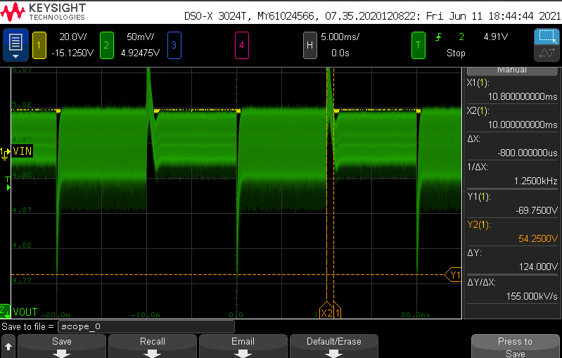
Can someone explain what is happening?

\$\endgroup\$

2 Answers 2

1
\$\begingroup\$

Because it enters into discontinuous mode (DCM). If the energy has nowhere to go, it is a good feature that this buck converter stops transfering more energy. So you cut-off the load meanwhile the converter dumped the energy from inductor to the output as every period. Since there was no load, the voltage increased over. Due to the loss in capacitor and feedback resistors, the voltage dropped below a threshold value and you got an extra pulse...and so on.

$$\dfrac{Li^2}{2} = \dfrac{Cv_o^2}{2} + v_o\cdot i_o$$

Since the output current is zero, then

$${Li^2} = {Cv_o^2}$$

The minimal on pulse "sends" a packet of energy to the output capacitor, the capacitance is the only responsible on how the final voltage amplitude will be.

Search in the datasheet for minimal on pulse time.

\$\endgroup\$
0
\$\begingroup\$

The reason is because that when the controller is regulating at one operating point, it takes the controller time to adjust its output to the new operating point. This means there will be an overshoot when load is removed and an undershoot when load is added. Every closed loop system has a unity gain crossover frequency that is determined by the frequency reponse of the converter in combination with the frequency response of the controller. The higher the unity gain frequency is, the faster the transient response will be.

According to the datasheet of the TPS5450, an internal type 3 compensation (controller) network as shown below is used: enter image description here

Because an internal controller is used, you can not adjust the controller parameters. The only thing you can control is the size of the output capacitor, which has an influence on the closed loop system response. You could try with a larger and smaller capacitor than the current one to see if the transient response improves.

\$\endgroup\$

Your Answer

By clicking “Post Your Answer”, you agree to our terms of service and acknowledge you have read our privacy policy.

Not the answer you're looking for? Browse other questions tagged or ask your own question.