1
\$\begingroup\$

enter image description here

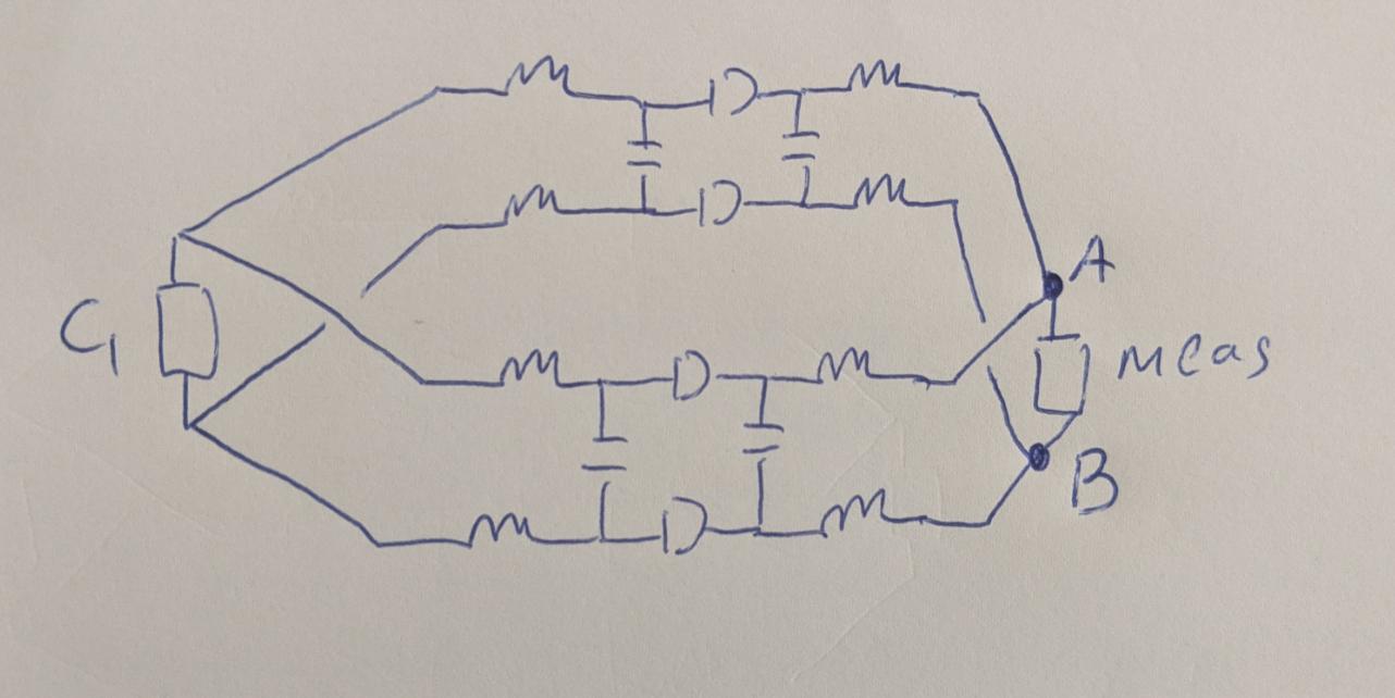
Hello everyone, I am currently trying to find the equivalent impedance of this circuit. The circuit consist of a load C1 which are connected to a two pole pi section with line inductors which are in parallel and at then end is just some sort of measurement block.

Was wondering if finding the equivalent impedance would be as simple calculating the parallel of the two line inductors and then adding in series with the load. After that the resulting impedance would be calculated in parallel with the capacitors from both pi sections.

Is this approach correct or should I do it differently?

\$\endgroup\$
4
  • \$\begingroup\$ What are the D-shaped elements in the middle supposed to be? \$\endgroup\$
    – Hearth
    Commented Jun 17, 2021 at 14:37
  • \$\begingroup\$ They are supposed to be series inductance and resistors, sorry for the vague drawing:) \$\endgroup\$ Commented Jun 17, 2021 at 14:38
  • 1
    \$\begingroup\$ Please clearly mark the (two) terminals across which you are planning to measure the impedance. \$\endgroup\$
    – AJN
    Commented Jun 17, 2021 at 15:35
  • \$\begingroup\$ @AJN I've edited the picture to include the terminals (A and B) where the impedance is measured. \$\endgroup\$ Commented Jun 17, 2021 at 16:02

1 Answer 1

1
\$\begingroup\$

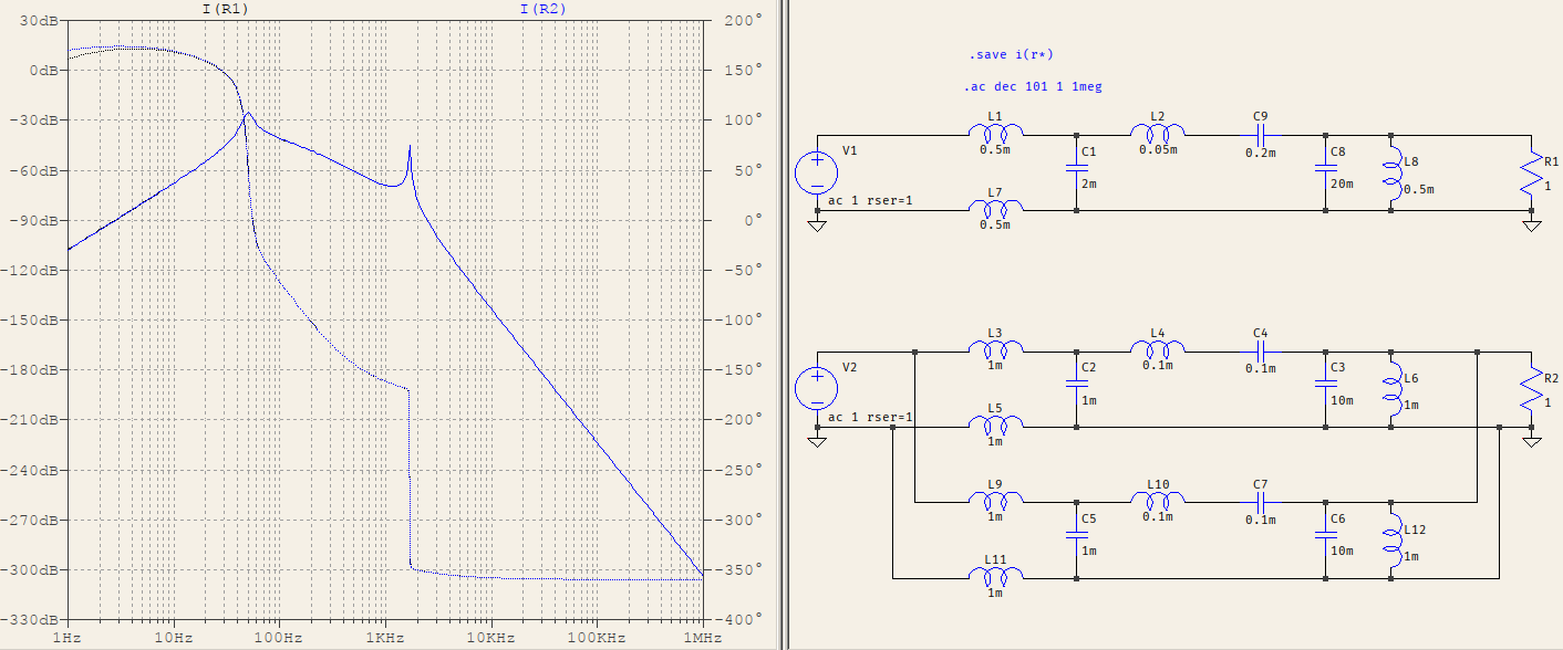
It will work if you apply the following reasoning, provided the network has two equivalent, symmetrical branches:

  • all inductances will be halvened
  • all capacitances will be doubled

test

This is a random example consisting of symmetrical LCL input, series LC, parallel LC. If the branches are not symmetric, trying to use the parallel-series equivalences will not work, due to the different loading effect on each branch. Don't forget that you're dealing with a passive network, so all the elements influence each other (more or less).


To be more precise about the nature of the imbalance: if two networks are placed on each branch and the elements are symmetrical, then the transfer function ends up with doubled poles and zeroes, which can be transformed into a single, equivalent branch, due to the order of the transfer function ending up the same.

But if the two brances are different then the number of poles and zeroes are now doubled, and a single branch can only have half their numbers, therefore the equivalence is impossible.

\$\endgroup\$
3
  • \$\begingroup\$ Thank you for the answer! yes in the case of the same circuit then the doubling of capacitances and halving inductances makes sense. Do you have idea how to approach this in the case where the branches are not similar (same structure, however different values of the inductors and capacitors)? \$\endgroup\$ Commented Jun 17, 2021 at 18:00
  • \$\begingroup\$ @radityaarrizki I don't think anything else will do it other than deriving the network topology by hand, or simply simulating it. Any imbalance will add additional poles/zeroes that a single branch cannot come up with. \$\endgroup\$ Commented Jun 17, 2021 at 18:05
  • \$\begingroup\$ I've edited my answer, I hope it's more clear now. \$\endgroup\$ Commented Jun 17, 2021 at 18:13

Your Answer

By clicking “Post Your Answer”, you agree to our terms of service and acknowledge you have read our privacy policy.

Not the answer you're looking for? Browse other questions tagged or ask your own question.