0
\$\begingroup\$

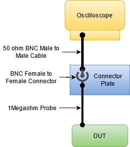
Connection Diagram

We have connected an oscilloscope and a function generator using a connector plate. We have terminated the signal connections from the oscilloscope & the function generator to the connector plate using a 50 ohm BNC to BNC cable.

The issue is if we connect a 1Mohm 10x probe to the connector plate the signal is not shown correctly. It is attenuated. I have kept the scope impedance to 1Mohm. If I connect the 1Mohm probe directly to the scope (bypassing the connector plate) then the signal is shown correctly.

Here I feel the issue is that the scope is connected to the connector plate using a 50 ohm cable and on the connector plate, we are connecting a 1Mohm probe (using BNC female to female connector) so this overall cable impedance is creating the issue.

Can anyone please help me on how to get the actual signal when we interface the 1Mohm probe using connector plate? Will a cable termination using a T connector help?

\$\endgroup\$
10
  • \$\begingroup\$ Sounds like you need a 50 ohm termination. \$\endgroup\$
    – winny
    Commented Jun 22, 2021 at 7:21
  • \$\begingroup\$ Show a schematic of the whole setup. The cable impedance is NOT the issue as that is a characteristic impedance (look up what that means) and not something you'd notice at low frequencies like 1 kHz. You have to learn about termination impedances. \$\endgroup\$ Commented Jun 22, 2021 at 7:31
  • \$\begingroup\$ Can you make a "picture" on HOW you are wiring exactly ? Fast generator require generally 50 ohm termination as said in comment ... \$\endgroup\$
    – user288518
    Commented Jun 22, 2021 at 7:33
  • 1
    \$\begingroup\$ How long is the cable from the scope to the plate? When you say '1Mohm 10x' probe, do you mean a probe designed to plug into a scope with 1Mohm termination (which would then have 10Mohm input resistance)? \$\endgroup\$ Commented Jun 22, 2021 at 10:58
  • 1
    \$\begingroup\$ Realize that you can only use an oscilloscope probe propely when they're connected directly to the oscilloscope. If you connect a cable in between the signal will be distorted! Maybe this video: youtube.com/watch?v=OiAmER1OJh4 will provide some insight. You call the probe "1 Meg Ohm", that means it needs to be terminated by 1 MOhm, which is in the oscilloscope. You added a wire and connectors in between that will add capacitance and your signals will be attenuated! An oscilloscope probe isn't designed to be used like that. \$\endgroup\$ Commented Jun 22, 2021 at 12:13

1 Answer 1

1
\$\begingroup\$

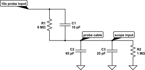
A 10x scope probe attenuates the signal using a 9 MΩ series resistor in the probe, which when combined with the 1 MΩ input resistance of the scope forms a 10 x resistor divider. This works fine for DC voltages, but the capacitance of the cable causes attenuation at higher frequencies. To compensate for this a small capacitor is placed across the 9 MΩ resistor so that a 10 x capacitor divider is also produced. The equivalent circuit looks like this:-

schematic

simulate this circuit – Schematic created using CircuitLab

C1 is the compensating capacitor which produces a 10x division in conjunction with C2 (probe cable capacitance) and C3 (scope input capacitance) that together total 90 pF. This circuit divides all frequencies by 10, so a low frequency square wave should be displayed with perfectly flat tops and bottoms.

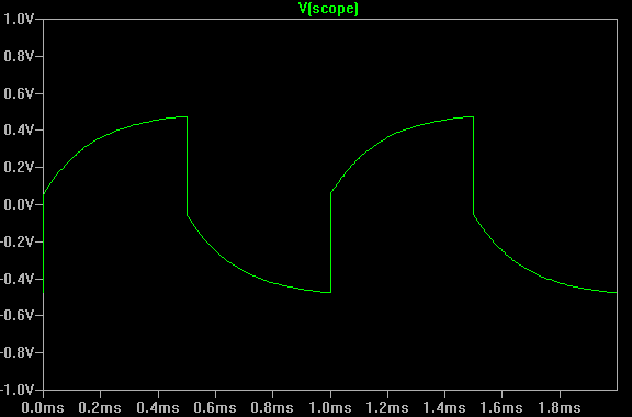
But what happens if you insert an extra piece of coax cable between the probe and the scope? Now the cable capacitance is increased so the capacitor division ratio is higher, causing reduced amplitude of higher frequency signals and distortion of low frequency square waves.

Typical capacitance of 50 Ω coax cable is 80~100 pF per meter. If we add another 90 pF to the cable part of the circuit above and 'measure' a 1 kHz square wave with it, we get this (simulated with LTspice):-

enter image description here

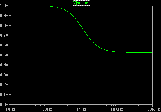
...and if we plot the frequency response (amplitude of a sine wave) we get this:-

enter image description here

This shows that even at 1 kHz there is significant attenuation.

Intuitively you may think that such small capacitances shouldn't have much effect at 1 kHz. But 1 MΩ is a very large resistance. Though the time constant of 1 MΩ x 90 pF is only 90 us, it takes many time constants for the signal to settle - and a 1 kHz square wave is only up or down for 500 μs at a time.

Bottom line:- a 10x passive probe should always be plugged directly into the scope.

\$\endgroup\$
1
  • \$\begingroup\$ Thank you Bruce for detailed description. I understood the problem. I thought using some termination, I may able to resolve this issue but from this description, it seems I need to change the design. Thank you. \$\endgroup\$ Commented Jul 20, 2021 at 9:51

Your Answer

By clicking “Post Your Answer”, you agree to our terms of service and acknowledge you have read our privacy policy.

Not the answer you're looking for? Browse other questions tagged or ask your own question.