8
\$\begingroup\$

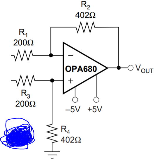
I have this circuit:

enter image description here

How would we calculate the input impedance of the differential amplifier?

I have read answers that says that the inverting impedance side will just be R1=200 ohm.

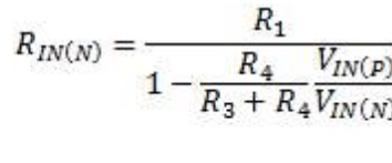
I have also read answers that say that the input impedance on the inverting side is this long formula:

enter image description here

The longer formula I found here.

I have also seen many other variations for what the input impedance of the differential amplifier on the inverting side and I'm lost.

Who is correct?

\$\endgroup\$
0

2 Answers 2

18
\$\begingroup\$

Short answer

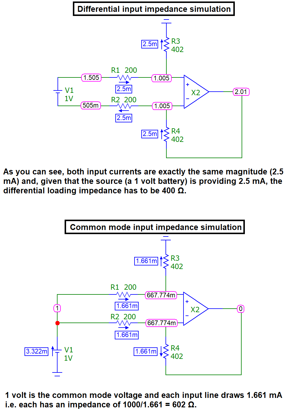
Using the values in your circuit, the common mode input impedance (to ground) is 602 Ω per input wire. The differential input impedance is 400 Ω. That's the short answer.

And, this assumes that the input voltage is sufficiently low so as not to cause op-amp saturation and, that the input frequency is low enough so that the gain-bandwidth-product of the op-amp produces enough open-loop gain so that we can assume ideal op-amp operation.

Simulations (a sanity check): -

enter image description here

I have also seen many other variations for what the input impedance of the differential amplifier on the inverting side and I'm lost. Who is correct?

There does appear to be a fair degree of BS about this basically simple circuit on the web (this site and wiki) so, if you don't believe me or still have doubts, use a simulator.


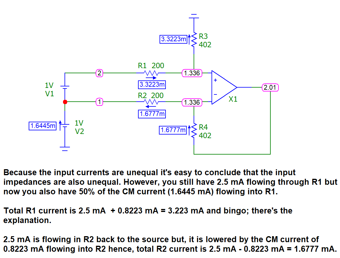
Some people over-analyse this circuit and get fixated on the two input voltages being independent. Quite easily you can mess up an analysis by doing this and, you'd likely observe that the individual currents into each input resistor are unequal in magnitude. But, this is because the applied analysis is imposing unreasonable constraints (compared to realistic and practical situations).

Inevitably, some folk conclude that the impedances into the two input resistors are unequal but, the reality is that you have a true differential balanced and bipolar input current (important) plus a superimposed common-mode current that "appears" to mess up the bipolar and balanced differential input currents.

In other words, don't mix up differential and common mode currents when making an analysis. If you do, you'll get confused. Example: -

enter image description here

This scenario DOES NOT allow you to conclude that for a regular differential signal source, the input impedances are not balanced.


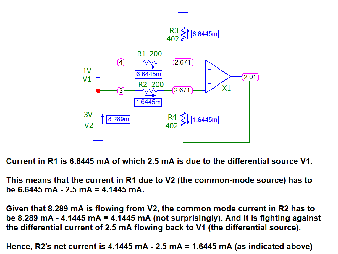
And, just for further clarity, if the CM voltage source is raised to 3 volts we see this: -

enter image description here

This adequately demonstrates the distinction between CM currents and differential currents and perfectly proves that, for the circuit above (R1 = R2 and R3 = R4), the differential impedance remains constant and the common-mode impedance remains balanced.

\$\endgroup\$
13
  • \$\begingroup\$ Is there any theory for the calculation in the last image? The result is correct but I wonder how do you can you apply the sum of common and differential currents like that as what you did is not superposition. For superposition, the negative terminal of V1 should be ground in the differential mode. \$\endgroup\$
    – emnha
    Commented Jun 27, 2021 at 17:55
  • \$\begingroup\$ Sure, there's theory behind everything like this @anhnha. \$\endgroup\$
    – Andy aka
    Commented Jun 27, 2021 at 18:08
  • 1
    \$\begingroup\$ Superposition theorem springs to mind @anhnha \$\endgroup\$
    – Andy aka
    Commented Jun 27, 2021 at 18:26
  • 1
    \$\begingroup\$ @AmitM if the differential amplifier circuit you are using is affected by reactive elements inside the components or on the PCB or in chips then you'd probably not use this circuit. But, for the majority of applications it won't make one bit of difference and, of course, it's easier to calculate with a DC source and, the simulation output calculates DC values for you so, all-in-all no, it's not better to use an AC source. But, this is a free world and you can make an answer that does use an AC source. I shall read it if nobody else does. \$\endgroup\$
    – Andy aka
    Commented Oct 24, 2022 at 15:36
  • 1
    \$\begingroup\$ Andy Aka, In your example, DC voltage source works fine as there are only resistance elements. If the pcb had capacitors or inductors, then I would use a 1V AC source in a simulator in the same way. \$\endgroup\$
    – Amit M
    Commented Oct 24, 2022 at 15:55
2
\$\begingroup\$

Since this question is high up on google searches, I think an answer that fleshes out Andy aka's (correct) answer with the corresponding theory that explains the intuition and simulations could be helpful. Also, I think the answer to the question

I have also seen many other variations for what the input impedance of the differential amplifier on the inverting side and I'm lost. Who is correct?

is "everyone" - because the input impedance people are calculating is all correct but mean different things.

First, let's start with the way the link https://e2e.ti.com/blogs_/archives/b/precisionhub/posts/overlooking-the-obvious-the-input-impedance-of-a-difference-amplifier does it (top image below)
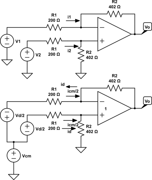
schematic

simulate this circuit – Schematic created using CircuitLab

With inputs V1 and V2, you get the currents $$i_2=\frac{V_2}{R_1+R_2}\\i_1 = \frac{1}{R_1}\left(v_1-v_2\frac{R_2}{R_1+R_2}\right)$$ The resistance at V2 is easy, but the apparent resistance (R=V/I) at V1 is a truly a function of V2. That is correct and reality, if you set up that circuit with some power supplies you can measure that and validate it. However, in practice, we don't use different amplifiers in that way, and that analysis is kind of difficult to think about and do on practical signals. What we really care about is what happens to signals that are differences (which is the wanted signal, V2-V1), and what happens to signals that are common mode (which are commonly unwanted noise, (V1+V2)/2). So we just define some new voltages and currents:

$$V_d = V_2-V_1\\ V_{cm} = \frac{V_1+V_2}{2} \\ i_d = \frac{i_2-i_1}{2} \\ i_{cm} = i_1+i_2$$

Which means: $$V_2 = V_{cm}+V_d/2 \\ V_1 = V_{cm}-V_d/2 \\ i_2 = i_{cm}/2+i_d \\ i_1 = i_{cm}/2-i_d $$

That gives us the bottom schematic in the figure above. The conventions for currents and voltages are chosen so that power is consistent (you can verify that): $$P_{cm}+P_d = P_1+P_2 = V_{cm}i_{cm}+V_d i_d = V_1 i_1 + V_2 i_2$$

Now we can find what the differential and common mode impedances are (i.e., what does each of those signals "see" as the impedance in the amplifier) $$Z_{cm} =V_{cm}/I_{cm} \\ Z_d = V_d/I_d $$

Substituting our new terms in to our previous solution:

$$i_d = \frac{i_2-i_1}{2} = \frac{V_d}{2R_1}\\ Z_d = 2 R_1$$

which is consistent with Andy aka's answer and intuition. For the common-mode solution:

$$i_{cm} = i_2+i_1 = V_{cm} \frac{2 }{R_1+R_2}-V_d\frac{R_2/R_1}{R_1+R_2}$$

Which gives us: $$ Z_{cm} = \frac{ \frac{R_1+R_2}{2}}{ 1-\frac{V_d}{V_{cm}}\frac{R_2}{R_1}}$$ which, again, is a bit complicated looking, but also is reality. Changing Vd can make Vcm's impedance apparently infinity. But that number also isn't necessarily that meaningful since differential impedance is what the signal would ultimately "feel" when given a Vd (what's the change in voltage per some change in current given Vd?).

$$\frac{\partial V_{cm}}{\partial i_{cm}} = \frac{R_1+R_2}{2}$$

That's the impedance the common mode source sees. Which is the same as if the common mode source was terminated by two parallel (R1+R2) to ground (which is Andy aka's answer as well).

So the answer to the question "who is right?" is basically "everyone," they're all just answering different questions. Thinking about the problem as the impedance the differential signal sees (the thing we care about) compared to the impedance the common mode signal sees (the part of the signal we typically try to eliminate in a difference amplifier) is probably more appropriate for most practical signals, and gives us a nice simple expression. However, as you can see, these impedances aren't that high - so in the end, most applications that really care about input impedances will just use an instrumentation amplifier anyway.

\$\endgroup\$
2
  • \$\begingroup\$ "However, in practice, we don't use different amplifiers in that way, and that analysis is kind of difficult to think about and do on practical signals." I read this as "yes, everything works out well if we make certain assumptions about the nature of the input". \$\endgroup\$ Commented Oct 24, 2022 at 15:30
  • \$\begingroup\$ @ScottSeidman interestingly enough there are no assumptions about the nature of the input in the analysis, and everything above is correct regardless of the input. The point is that sometimes talking about the inputs in a different (yet mathematically identical) way can help. For example, I can give you coordinates on Earth based on the heading and distance from great pyramid at Giza, or I can give you latitude and longitude. Both are correct, but sometimes it's easier to use latitude and longitude, and sometimes it's easier to talk about it relative to the great pyramid. \$\endgroup\$
    – KD9PDP
    Commented Oct 25, 2022 at 21:27

Your Answer

By clicking “Post Your Answer”, you agree to our terms of service and acknowledge you have read our privacy policy.

Not the answer you're looking for? Browse other questions tagged or ask your own question.