1
\$\begingroup\$

I looked through lots of questions, but I didn't find a suitable answer for the project I'm working on. The project can be thought of as a simple control box, water valve, and scale.

enter image description here

The mcu control board inside the valve receives a binary on/off signal to control the flow. The mcu control board inside the scale has an ADC which interfaces with a load cell, and it sends the digital reading over a long shielded cable. The scale control board has appropriate lowpass filters and proper shielding, so the ADC readings themselves are very clean.

My problem has been infrequent spikes in digital readings. I believe it is due to the noisy environment the cable is routed through, and inductive spikes in the cable. The digital communication is simply using GPIO pins with a driver/buffer chip on each end of the cable.

My initial approach was to keep a 5 frame rolling average, and reject a reading if it is outside the mean of the readings +/- a predetermined value. This had issues with the third graph shown being entirely rejected, and didn't account for increases in flow rates. I was considering using a calculated flow/delta rate as the threshold, but decided to see if a better solution exists before trying to reinvent the wheel. The main controller needs to retain a good time response to shut off the valve accurately, and the ADC is selectable to be 10 or 80 samples per second.

I am wondering if anyone has encountered a similar problem and fixed it with a simple solution. All I need to implement is a way to throw out signal readings if it is a temporary spike, but keep the readings if it remains high. I am partly asking in case someone in the future searches the internet and finds this question.

Here are some graphs which demonstrate:

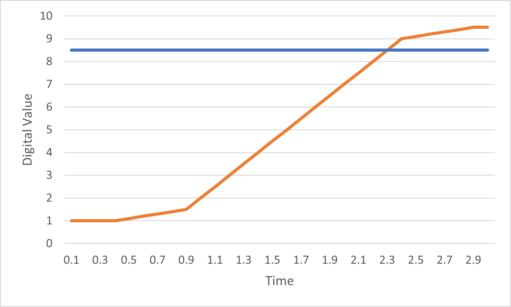
This is a typical operating cycle. Valve turns on, and when the reading hits the fill threshold (blue), it turns off.
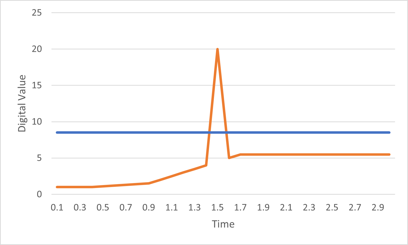
enter image description here This is an example of the problematic reading. An outlier in the signal trips the valve early, and the real value of the fill ends up being too low.
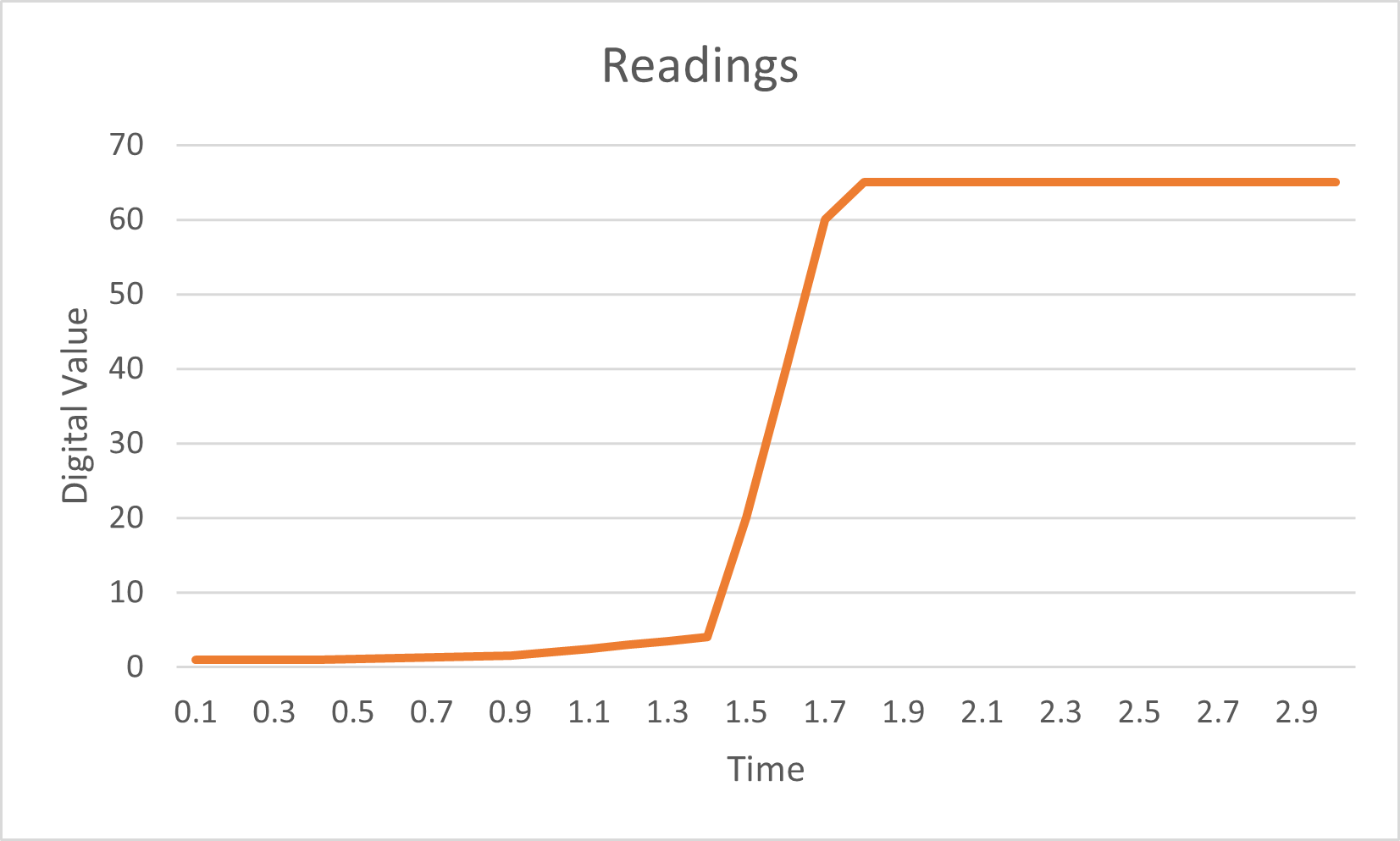
enter image description here This is what happens when the scale is calibrated or used as a part counter. This spike remains high, and does not need to be rejected. These values are much higher than the filling values.

\$\endgroup\$
3
  • \$\begingroup\$ Why was the third graph entirely rejected ? since the data is averaged by a moving average filter with window size 5, wouldn't the signal have been accepted from (at least) the fifth high sample onwards ? \$\endgroup\$
    – AJN
    Commented Jun 30, 2021 at 17:59
  • \$\begingroup\$ @AJN A typical rolling average filter wasn't working very well due to the magnitude of the spikes reported, so it was modified to throw out the value entirely, which left the rolling average too low (and subsequently rejecting all values)... not a good solution I will admit. Example of a spike could be 25g, 26g, 5000g, 27g, 28g throwing off the moving average to the point of rejecting good values for 5 full frames (half a second). On the part counter, an example would be 1g, 1g, 1200g, 1200g, 1200g \$\endgroup\$
    – zozwold
    Commented Jun 30, 2021 at 18:17
  • \$\begingroup\$ Understood. I imagined that the sample is discarded from being used for final application, but not from being used for next instants averaging. \$\endgroup\$
    – AJN
    Commented Jun 30, 2021 at 18:20

3 Answers 3

1
\$\begingroup\$

The method I have used in the past that works well is track the rolling 3sigma and exclude if it exceeds the range. This works if your S/N ratio is >100. You can adjust sigma multiple according to expected short term number of values computed and rate of change of signal.

This could be using the rolling mean of signal-squared values with the min/max range as an inclusion range with a tolerance added for thresholds for changing inputs.

I have also used analog S/H with differential filters to inhibit transfer of the hold value to the ADC input. Also I have used converting to digital locally and adding parity or hamming code for long links.

But ultimately tracking down the source of interference to improve SNR is best. I would use look for EMI correlation … (even a soldering iron thermal controlled relay can cause a glitch) and if failed, do ingress susceptibility tests with a magnetic coil noise generator.

You may want to change the GPIO to differential balanced RS485 or simply add 150 Ohms to the driver to approach matching a 200 ohm cable to eliminate mismatch ringing on twisted pair.

\$\endgroup\$
1
\$\begingroup\$

You might try a median filter. This kind of filter is designed to reject a small number of grossly incorrect samples from a set of samples. A typical approach is to output the median value from 5 input samples.

\$\endgroup\$
0
\$\begingroup\$

One easy way to remove outliers is to take the differential of the signal and remove anything above or below X threshold.

Another way to do this is to use a median filter and subtract it from the raw data then detect outliers by threshold at a certain value.

You could then replace the outlier point with the previous value, or take the average of the next and previous value and replace it with the average of the two (which would be like drawing a line through the points)

Threshold only works if all the outliers don't look like signal.

\$\endgroup\$

Your Answer

By clicking “Post Your Answer”, you agree to our terms of service and acknowledge you have read our privacy policy.

Not the answer you're looking for? Browse other questions tagged or ask your own question.