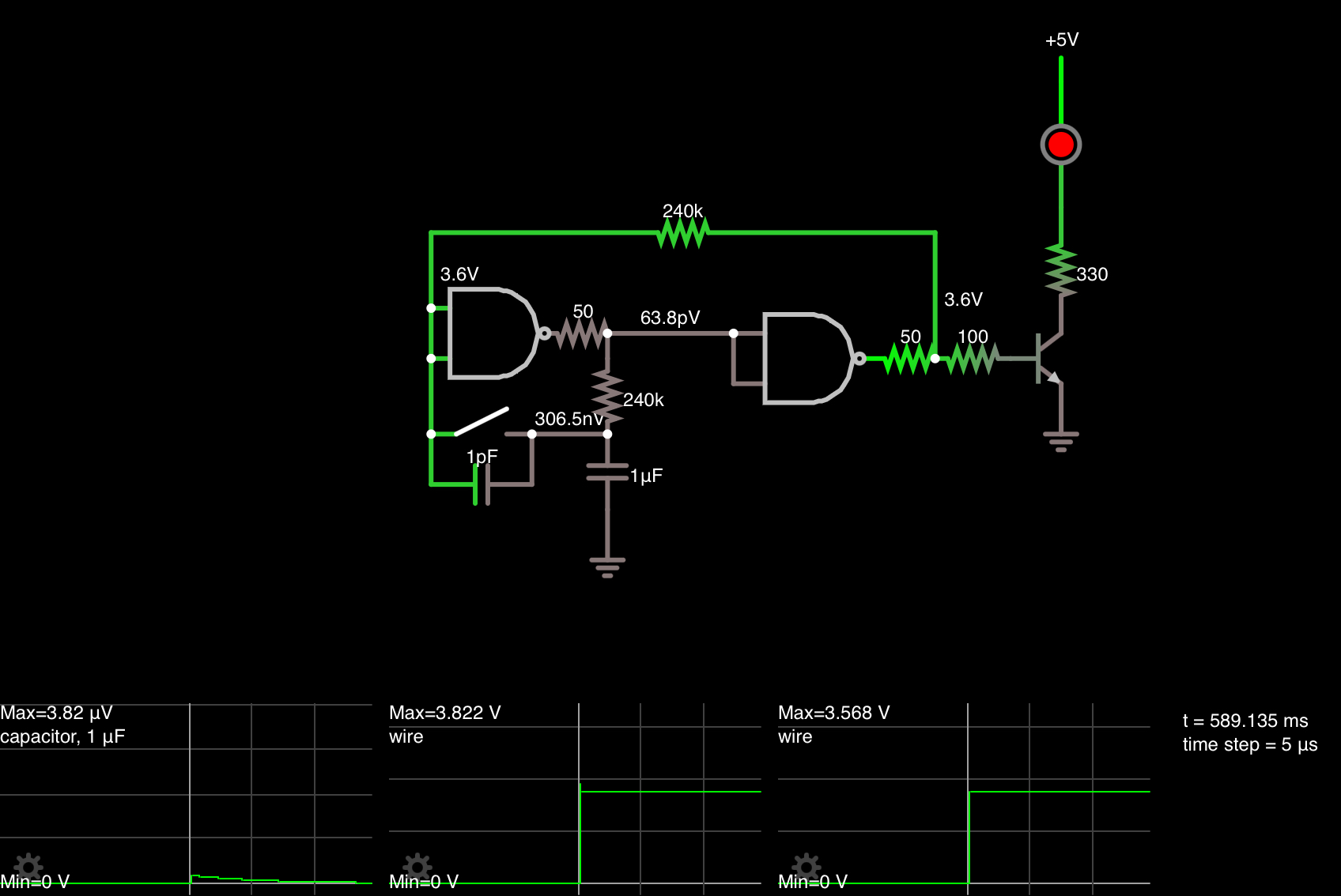
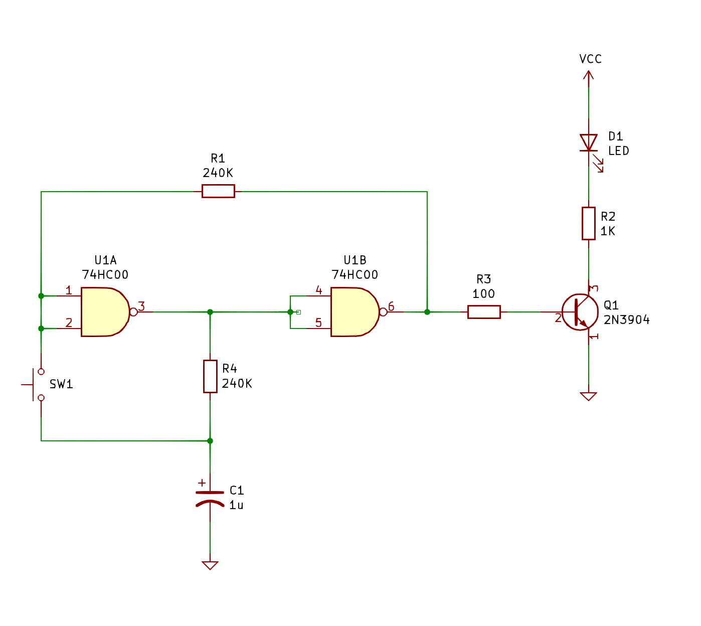
With Vcap=0 on power up and positive feedback with some RC delay, this ensures the output is always off on startup. Connecting the cap between V+ And input would have the opposite effect.
Revised answer:
This is a metastable condition with a race to see which input reaches the crossover threshold which is expected to be equal for all devices in the same IC.
My hypothesis is that the switch adds some 1 pF to the 0V cap and that may be enough to assert the 1st gate losing the race and forcing the output high when they both are expect to transition when Vcc exceeds 1.2V or just around the Vgs(th) of the CMOS gate.
so I simulated it and everytime, the LED is OFF on reset, but if I pull off the 1pF across the button, the LED is ON after reset as expected.

The proof is hard to scope but easy to verify. Moving the 1uF cap from ground to Vdd (if non polar) will invert the LED on power up. If it stays off then it is the other theory that the 100 ohm load reducing Voh by 1/3 above Vbe due to the internal RdsOn being 50 ohms nomonal at 5V is the correct answer and this one is just a SWAG or incorrect.
Anyone care to place any bets?
In any case, R3 can be increased to 10k easily. But th 100 ohms and the transistor has no effect on this on the 50 ohm 74HC driver, except to reduce the Voh levels by 25% or so.
In either case if you want it ON, add 100 pF or more across the switch (or to 0V) and change R3 to 10k.


