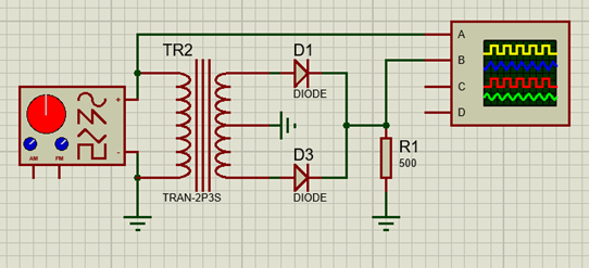
In my class, we are using Proteus 8 to simulate simple rectifier circuits. We are not familiar with analog electronics yet. Since the class is all about using engineering software, there are not many explanations for the theories.
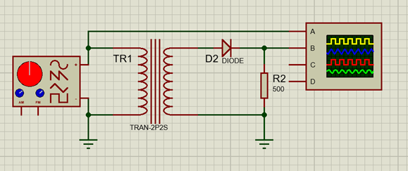
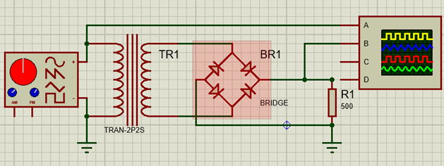
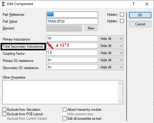
In this particular class, we tried 3 different rectifiers including half-wave, center tap, and bridge rectifier. I applied the same signal and resistor value to all of the circuits, 6V,10Hz, RL = 500ohm, 1:1 ratio for all transformers, and the same setting for both the oscilloscope and signal generator.
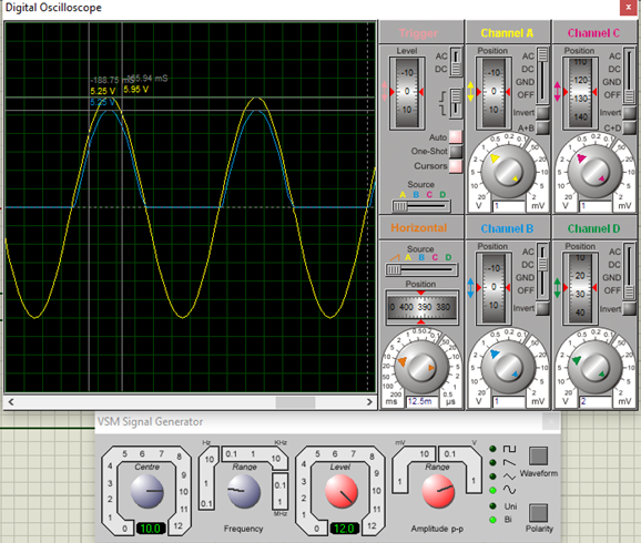
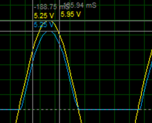
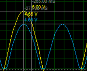
I was able to figure the half-wave and the bridge rectifier's output voltages. The half-wave rectifier's output voltage is 5.25V (5.3V) because of the diode's voltage drop 6V-0.7V, while the bridge rectifier got 4.65V(4.6V) because the current goes through 2 diodes in each cycle 6V-0.7V-0.7V.
Half-wave rectifier:
Bridge rectifier:
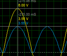
Now for the real question. From what I understand, since the voltage is divided across the secondary winding, each cycle has 3V. If current only passes through 1 diode in each cycle, shouldn't the amplitude be around 2.3V?
I know it should be more complicated. From what I understand, it should include something like Vrms, Vavg which includes integrals, or something like that, but I turned the output channels to DC instead of AC as per my lecturer instructed so that I can only calculate it as in DC analysis, so I'm confused right now. I'm not sure if this all makes sense at this point, hope anyone would help me understand better, thank you for reading this far.

