0
\$\begingroup\$

Periodic square wave feeding an RC circuit:

Periodic square wave feeding an RC circuit

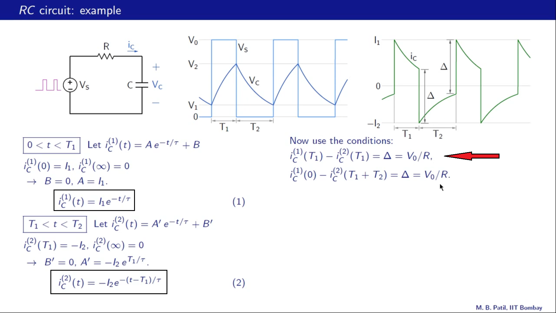
I am currently studying RC filter response to a square wave input with a period of \$ T_1 + T_2 \$.

I have understood about voltage expressions and current expressions, but I don’t understand why:

\$ \textbf{$\Delta$ = $ \frac{V_0}{R}\ $} \$

The right most graph in green is of \$i_c\$ current through the capacitor and \$\Delta\$ is the current jump. I don’t understand the jump.

\$\endgroup\$

1 Answer 1

2
\$\begingroup\$

Δ is that current jump and that is what I don’t understand

To understand change in Current during switching instant -

just before t=T1

Voltage drop across resistor =$$V_R=V_s-V_c$$ $$\implies$$ $$I_1=\frac{V_s-V_c}{R}$$

Just after t=T1

Voltage drop across resistor =$$V_R=-V_c$$ $$\implies$$ $$I_2=\frac{-V_c}{R}$$

Hence ,$$∆=I_1-I_2 =\frac{V_s}{R}$$

\$\endgroup\$

Your Answer

By clicking “Post Your Answer”, you agree to our terms of service and acknowledge you have read our privacy policy.

Not the answer you're looking for? Browse other questions tagged or ask your own question.