0
\$\begingroup\$

I've built the following circuit on a breadboard (for the purpose of experimentation) and measured the voltages: enter image description here
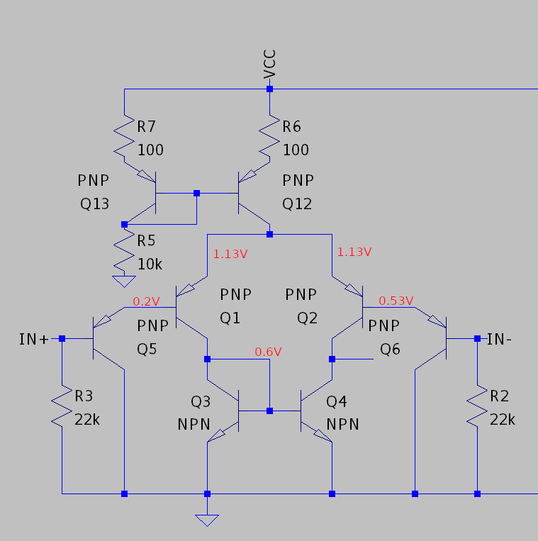
IN+ and IN- are connected to ground, VCC is 10V.

As you can see it's a differential pair (using 2N3904 and 2N3906) loaded with a current mirror for differential to single-ended conversion. The input uses Q5 and Q6 to raise Q1 and Q2 base voltages so that they're turned on even when the IN+ and IN- are grounded. LTSpice simulation seems to confirm the circuit works, but on a breadboard Q5 is saturated.

I tried the following things to try to fix the circuit:

  1. Diode-connecting the other side of the mirror instead, but then Q6 would become saturated.
  2. Replacing Q3 and Q4 with same value resistors - this seemed to help with biasing, but that I think cuts the gain in half.
  3. Replacing Q3 and Q4 with some other transistor (2N2222) - this didn't make a difference.

I was hoping that it would work, even considering the obvious parameter mismatch between discrete transistors. Any ideas what am I missing?

\$\endgroup\$
15
  • 1
    \$\begingroup\$ Your measurements suggest Vbe of Q1 is 0.9V. That should tell you something is wrong either with your measurements, or with Q1. \$\endgroup\$
    – user16324
    Commented Aug 7, 2021 at 14:39
  • \$\begingroup\$ The inputs are labelled the wrong way around. \$\endgroup\$
    – user173271
    Commented Aug 7, 2021 at 15:03
  • \$\begingroup\$ I find 0.524 V in place of 0.2 V \$\endgroup\$
    – Antonio51
    Commented Aug 7, 2021 at 15:11
  • \$\begingroup\$ DC gain is about 33db. Phase strange. Follower ~ok. Will try square waves. \$\endgroup\$
    – Antonio51
    Commented Aug 7, 2021 at 15:23
  • \$\begingroup\$ Square wave input 5 kHz 2mV pp (around 0V) ... Output 761 mV to 866 mV, gain 47, trise=4 us, no overshoot. \$\endgroup\$
    – Antonio51
    Commented Aug 7, 2021 at 15:42

1 Answer 1

0
\$\begingroup\$

As @user_1818839 pointed out in the comment, there was an error in measurement that I've made. The 0.9V across emitter-base of Q1 is simply out of this world, and should have made me think twice before posting - lesson learned :-)

\$\endgroup\$
10
  • \$\begingroup\$ Any particular reason you chose \$22\:\text{k}\Omega\$ resistors? Those will just haul the whole thing down, with those Darlington inputs there. Also, you've got no place for the current to go out of the node occupied by the collectors of \$Q_4\$ and \$Q_6\$. Is that intended? \$\endgroup\$
    – jonk
    Commented Aug 7, 2021 at 18:09
  • \$\begingroup\$ jonk@, thanks for asking. What I'm doing here is trying to build an amp similar to the LM386, using discrete transistors, and also play around a bit with differential pairs. In LM386 they use 50k resistors to do two things I think: 1. Provide a path for the base current to flow. 2. Setup the input impedance to 50k. I've had 22ks lying around, so picked them instead for now. What do you mean by "they will haul the whole thing down"? \$\endgroup\$
    – npnman
    Commented Aug 8, 2021 at 8:59
  • \$\begingroup\$ As for the "no place for the current to go", I suppose you mean Q4 and Q2 (Q6 is shifting the voltage up, sorry for the small and confusing diagram) and by the "current" you mean the small-signal current reflected back by the Q4 and small-signal current originating from Q2? In that case, I'm aware this is a problem, and that I'll need to connect this node to some kind of common-emitter in the next stage (at the moment the fact that the current has nowhere to go pretty much drives Q2 to the edge of saturation). \$\endgroup\$
    – npnman
    Commented Aug 8, 2021 at 9:05
  • \$\begingroup\$ Your schematic doesn't recognize the \$\pi\$-structure used in the LM386 (or LM380.) No gain-setting resistors between emitters. I suppose that also threw me off a a bit. So it helps to know what you are about, now. By "haul the whole thing down" I meant the resistors are so low that the base currents can't yield much drop. But then this is an LM386. My mistake. \$\endgroup\$
    – jonk
    Commented Aug 8, 2021 at 15:29
  • \$\begingroup\$ And yeah. I was having a hard time reading which BJT was labeled by what label. My mistake there, too. And okay. That's explanation enough. A final note, You should do some "design work" if you are going to "go discrete." BJT variation is large and the reaction to temperature varies too, though I admit a lot of problems can be swept under the NFB rug. But I'd probably want to think some before just taking what appears to be a semi-behavioral copy from a datasheet. Do you understand, in detail, what the current in the 15k resistor does and where it goes and why? \$\endgroup\$
    – jonk
    Commented Aug 8, 2021 at 15:37

Your Answer

By clicking “Post Your Answer”, you agree to our terms of service and acknowledge you have read our privacy policy.

Not the answer you're looking for? Browse other questions tagged or ask your own question.