1
\$\begingroup\$

I have a 24V motor which is driven bi-directionally with PWM using DRV8873 H-Bridge motor controller.

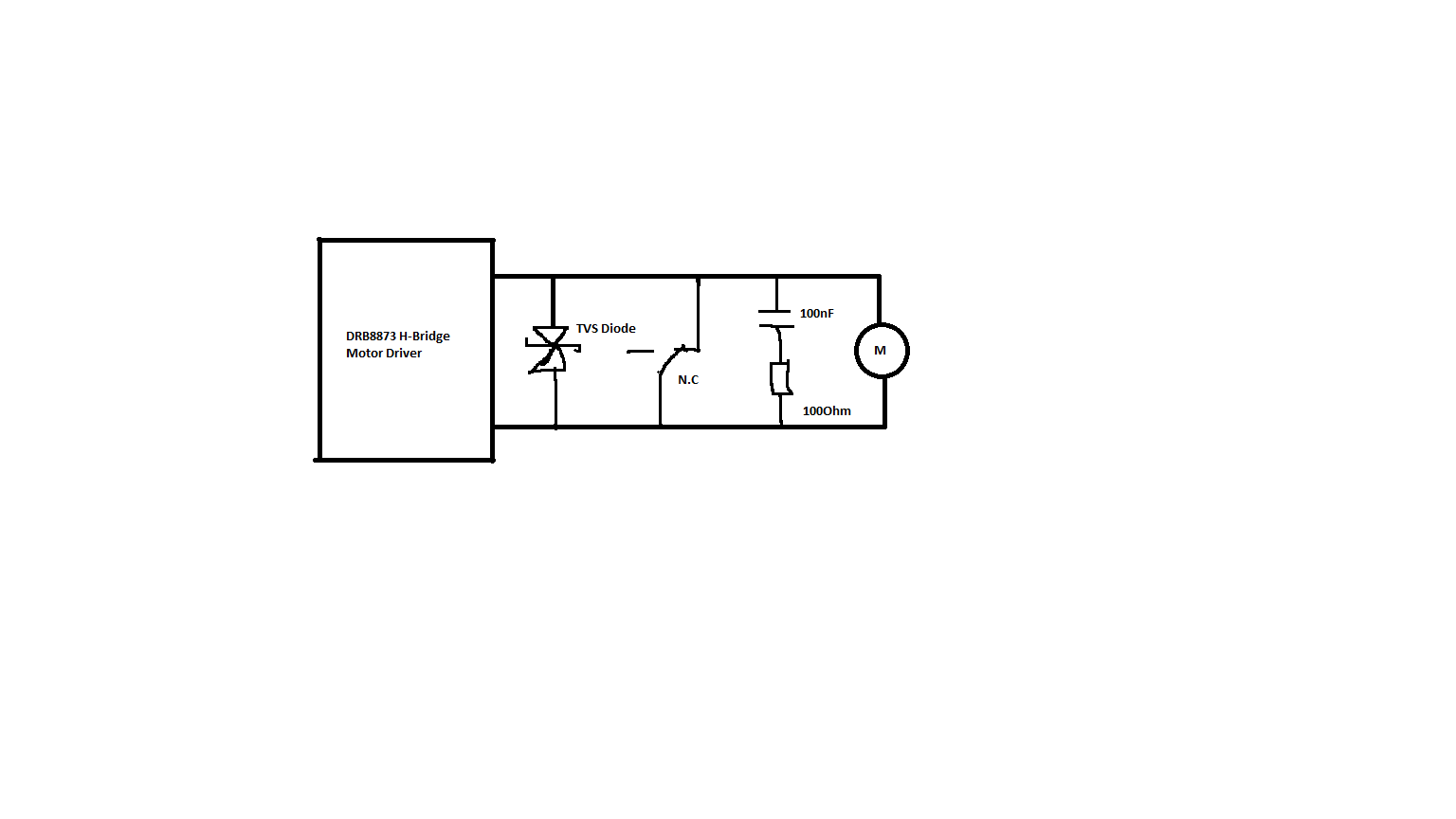
The circuit looks as follows:

enter image description here

For normally driving the motor in either of the direction, I switch the relay, which removes the short and I apply PWM.

While braking the motor, I first make a short at the motor controller, wait for 150ms and switch the relay back to normally closed to keep the motor in this state.

A HFD4-I/24 signal relay is used to keep motor at the braking position.

enter image description here

In this case sometimes the relay gets stuck when the motor is driving high loads. It gets back to normal when I restart or give it a flick.

We are assuming it is because of contact arcing.

I have tried using both contacts of the relay in parallel. I tried to use different relays with a higher contact rating, but nothing helps.

I can't go any higher because of the spacing issue. The relay should be as small as possible.

I am driving the motor with 24V PWM drive, maximum allowed current 2A through the motor.

It would be really helpful if anyone has some ideas.


I was measuring the current and voltage peaks with Osci(No load) and observed there was no voltage spike at all. I had a current spike of max 2A(for 10ms without any load) flowing through the relay when the motor was braked. It seems to be impossible to do measurements with my setup at full load. Possibly the current spike will be much higher with full load.

No load motor current : 200mA

Please correct me if my understanding is wrong:

My relay contact seems to have contact rating of 1A at 30VDC. If I use 2 contacts parallelly, then when I make a short at motor, the current spike should divide between 2 contacts and go back to the motor. If my peak is higher than 2A, the contacts get hot and gets micro welded?

What I am unable to grasp is why the voltage was perfectly smooth when the motor terminals were shorted but the current was spiking up for a short period. As I understood, the motor like an inductor, will resist change in the current inturn causing voltage spikes.

Can anyone explain me?

Thanks!

\$\endgroup\$

1 Answer 1

2
\$\begingroup\$

It would be really helpful if anyone has some ideas

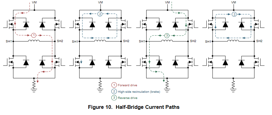
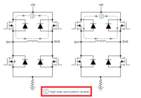
You seem to be missing what your diagram is telling you: -

enter image description here

In other words, you don't need a relay contact to short the motor terminals because the MOSFETs can be persuaded to do that.

Neither should you need a TVS diode across your motor because the bulk diodes inside the MOSFETs (shown as real diodes in your picture) will return back-emfs to the power rails - you just need to ensure there is enough bulk-capacitance across the power rails to be able to soak up back-emf energy. The snubber may also not be required.

\$\endgroup\$
4
  • \$\begingroup\$ Thanks for the suggestion Andy. I am aware of using MOSFETs to short the motor terminal. The relay was intentionally used to keep the motor rotor in the same position, even when there is no Power supplied to the circuit. The motor is used in opening and closing the windows. The window has to stay in open position even when there is no power delivered. I have a 220uF bulk capacitor at the power rails placed near the driver. I can get rid of TVS and Snubber. But will that help me in getting rid of Arcing problem? \$\endgroup\$
    – Elektrobot
    Commented Aug 13, 2021 at 12:35
  • 1
    \$\begingroup\$ @Elektrobot use the MOSFETs to remove the energy from the motor and then use the relay when the circuit power is removed (although I don't think it'll do a fantastic job of holding the armature in an exact place - I've had garage door roller/shutter experience on this). \$\endgroup\$
    – Andy aka
    Commented Aug 13, 2021 at 13:01
  • \$\begingroup\$ I think I am doing exactly like this. When I am braking the motor first I switch the MOSFETs to make a short and wait for 150ms and switch ther relay back to normally closed . When I want to run the motor forward opr backwards switch the relay to Open and turn on the MOSFETS for forward or reverse drive. But I don't understand why the current spike is going through the relay. \$\endgroup\$
    – Elektrobot
    Commented Aug 13, 2021 at 13:13
  • 1
    \$\begingroup\$ Why don't you just use the relay when power is removed. \$\endgroup\$
    – Andy aka
    Commented Aug 13, 2021 at 13:40

Your Answer

By clicking “Post Your Answer”, you agree to our terms of service and acknowledge you have read our privacy policy.

Not the answer you're looking for? Browse other questions tagged or ask your own question.