0
\$\begingroup\$

If I want to compute the junction temperature of a component, I can by using its thermal resistance (case to junction) and if I know the power dissipated by the component and the temperature of the case. It allows to know the difference of temperature between the junction and the case of the component in steady state only. In other words, it means that the different heat capacitors of the component are charged to their steady value.

If I took a diode, the average power dissipated over a period is given by the following formula:

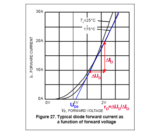
$$P_d = U_{D0}*I_{average} + R_{d}*I_{rms}^2$$

If the current through the diode is DC, which is not my case, the previous formula can be simplified:

$$P_d = U_{D0}*I_{DC} + R_{d}*I_{DC}^2$$

where Ud0 and Rd are extracted from the below curve:

enter image description here

Now what s the purpose of thermal impedance?

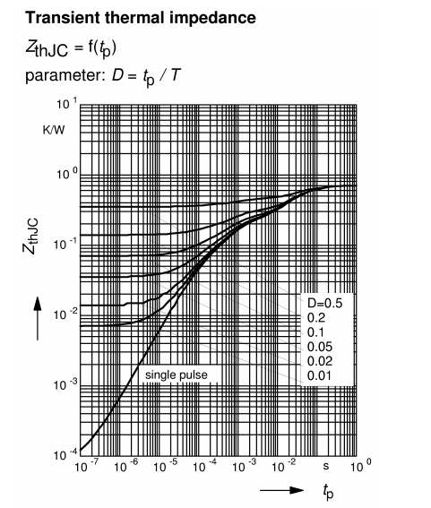
Here is a thermal impedance extracted from a datasheet:

enter image description here

It gives the thermal impedance of the junction to case of the component in function of the duty cycle of the power. In acSMPS, the component dissipates power only (almost) when it conducts.

Nevertheless in the previous calculation, we have also considered the fact that the power was not DC by taking the average current and the rms current.

I do not understand the difference. What should I use?

\$\endgroup\$
9
  • \$\begingroup\$ For DC, you only need thermal resistance. For pulsed applications, you need to take into account thermal impedance. \$\endgroup\$
    – winny
    Commented Aug 20, 2021 at 7:53
  • \$\begingroup\$ I do not get why the first "themal resistance" does not take into account the effect of pulsed application as the average power dissipated is calculated via RMS and average current. \$\endgroup\$
    – Jess
    Commented Aug 20, 2021 at 8:00
  • 1
    \$\begingroup\$ At the start of the pulse the junction is surrounded by a cold chip. At steady state it is surrounded by a hot chip. \$\endgroup\$ Commented Aug 20, 2021 at 8:32
  • \$\begingroup\$ Did you want a formula for estimating the junction Rjc(f,d) to add to Rjc(dc)? If you know the thermal time constant of the heatsink… \$\endgroup\$
    – D.A.S.
    Commented Aug 20, 2021 at 13:31
  • \$\begingroup\$ @TonyStewartEE75 I am sorry I do not get what you said ? For estimating what ? Rjc(f,d) f for frequency and d for duty cycle ? And what is Rjc ? The thermal Impedance ? \$\endgroup\$
    – Jess
    Commented Aug 20, 2021 at 13:38

1 Answer 1

3
\$\begingroup\$

It takes time for the heat to conduct away from the hotspot, and the thermal resistance does not take that into account as that's DC usage.

So if on average your component dissipates 1W into heat, there is a big difference how much the internal silicon junction heats up momentarily, if you have a constant 1W dissipation at DC, or if there is 10W dissipation for 10% of the time where it heats up rapidly and 90% of time it is let to cool down to let the heat conduct away.

\$\endgroup\$
1
  • \$\begingroup\$ Well, I think I get it. So I calculated the average power dissipated through the diode according to the formula mentionned. Now, according to the waveform of the dissipated power, if it is DC or pulsed, the equivalent thermal model is not the same. In the DC model, there is no heat capacity as it is charged, and in the case of the pulsed model, the thermal impedance given corresponds to the modelization of the heat capitor and the thermal resistor ? It includes a notion of heat variation over the time and its average this variation something like that \$\endgroup\$
    – Jess
    Commented Aug 20, 2021 at 10:02

Your Answer

By clicking “Post Your Answer”, you agree to our terms of service and acknowledge you have read our privacy policy.

Not the answer you're looking for? Browse other questions tagged or ask your own question.