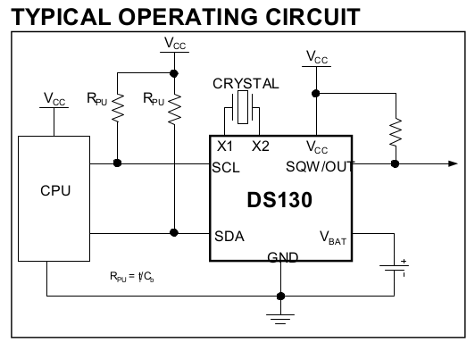
I want to build an RTC clock for the Raspberry Pi. Adafruit has a guide to accomplish this with Dallas DS1307. On the schematic they put a 2.2K resistor between VCC and SCL and do the same for VCC and SDA. SQLW is just wired out. But on the IC's datasheet, the resistors are proposed to be elsewhere:
Serial Data Input/Output. SDA is the data input/output for the I2C serial interface. The SDA pin is open drain and requires an external pullup resistor. The pullup voltage can be up to 5.5V regardless of the voltage on VCC.
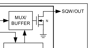
Square Wave/Output Driver. When enabled, the SQWE bit set to 1, the SQW/OUT pin outputs one of four square-wave frequencies (1Hz, 4kHz, 8kHz, 32kHz). The SQW/OUT pin is open drain and requires an external pullup resistor. SQW/OUT operates with either VCC or VBAT applied. The pullup voltage can be up to 5.5V regardless of the voltage on VCC. If not used, this pin can be left floating.
So the question is: why there is a resistor at SCL and why there isn't any at SQW?


