1
\$\begingroup\$

After some months I went back to try to make my AM radio work.

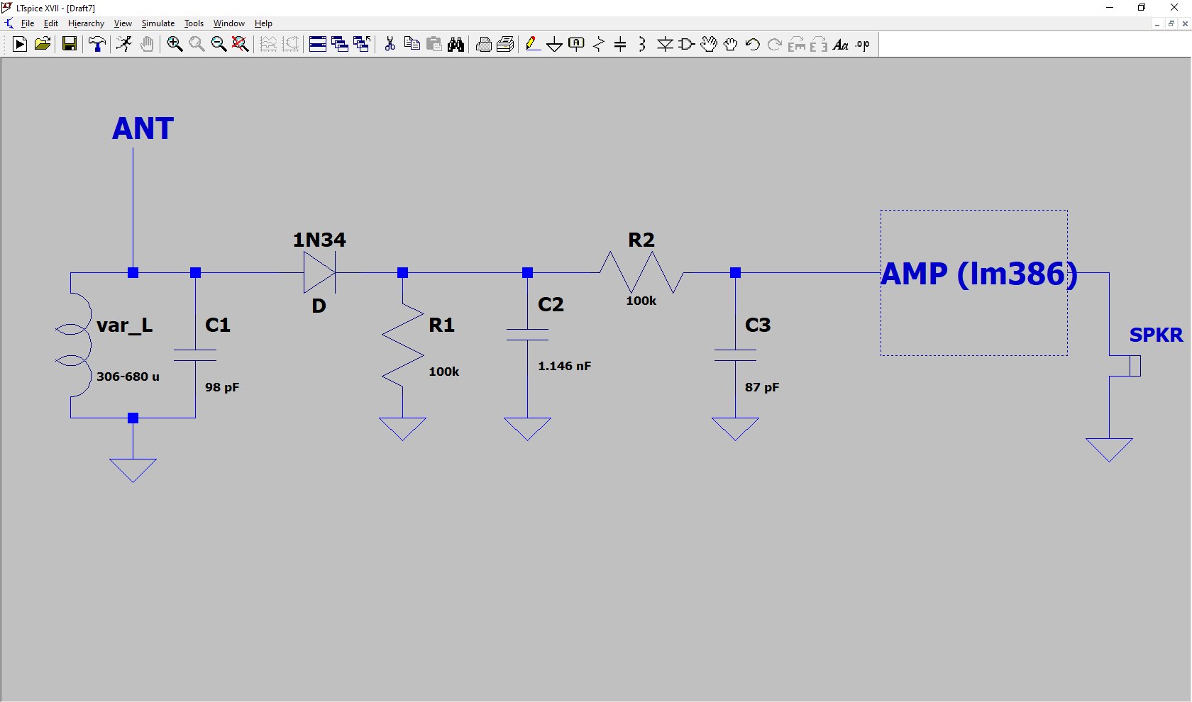
This is the schematic:

Radio schematic

ANT is a 16 meters long straight copper wire (insulated).

R1 and C2 gives a time costant \$ \tau = 114 \, \mu s\$ in between the fast carrier and the highest audible frequency. R2 and C3 is low pass filter with a cut frequency of \$ 18000 \, Hz\$ to get rid of the carrier wave. AMP is the amplification stage done with an LM386 and 200 gain.

The fact is that I cannot tune to any station (I have a commercial radio that can pick up AM station, so I know there are some) and only hear static. I've seen many schematic like mine and some put a capacitor in the pF range at the foot of the antenna (but none explain the purpose of it, so I don't know why it should go there) so maybe that is the problem.

\$\endgroup\$
7
  • \$\begingroup\$ I'd start by removing C2. It looks like a short circuit to the radio signal. \$\endgroup\$
    – JRE
    Commented Aug 30, 2021 at 8:40
  • \$\begingroup\$ C2 is fine at that value but I'd consider dropping R1 to 10 kohm so that the diode is operating more cleanly as a rectifier. You didn't mention what AM frequency range you are trying to operate over. \$\endgroup\$
    – Andy aka
    Commented Aug 30, 2021 at 9:15
  • \$\begingroup\$ @JRE C2 is necessary to create the an RC circuit that can demodulate the AM transmission \$\endgroup\$ Commented Aug 30, 2021 at 10:02
  • \$\begingroup\$ @SirLeoncavallo: The diode demodulates the RF. The other stuff filters out the high frequency stuff left over after demodulation so that you can pass the audio to your amplifier. \$\endgroup\$
    – JRE
    Commented Aug 30, 2021 at 10:05
  • \$\begingroup\$ @JRE But the diode should only act to cut the negative voltage, so that we have only the positive part of the carrier frequency and the RC can "trace" the profile of the carrier so that we have the audible frequency that was encoded in the carrier, or I'm wrong?(The source to what I'm saying is THe Art of Electronics, page 56) \$\endgroup\$ Commented Aug 30, 2021 at 10:22

2 Answers 2

1
\$\begingroup\$

2 things to do :

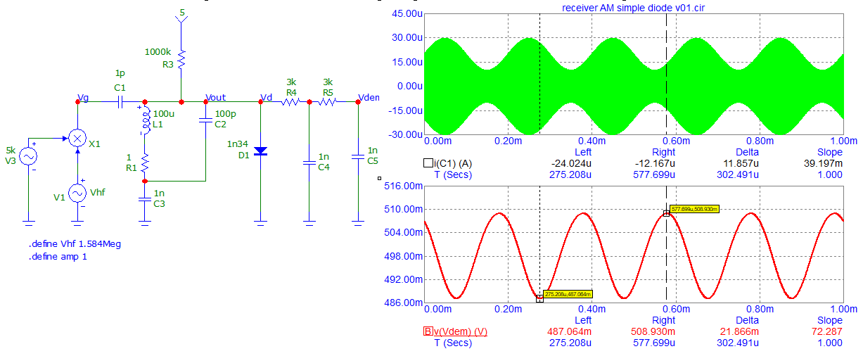
1- "put a capacitor in the nF range at the foot of the antenna" as you have seen.

2- Add a resistor to "polarize" a little the diode ... (via left side).

Target : This is done to make use of the "parabolic" curve of the diode at low levels. This is not an "envelope detector".

<<< I've seen many schematic like mine and some put a capacitor in the pF range at the foot of the antenna (but none explain the purpose of it, so I don't know why it should go there) so maybe that is the problem. >>>

Now, you can see that the capacitor at the foot ... will lock the DC part and allow the diode to be well polarized.

So, we use the non linear part of the characteristic of the diode for "demodulating" wave received. NB : signal demodulated is "weak". The coupling to the "antenna" (sine wave modulated generator) is done with a 1pF capacitor, for "not changing" the characteristic of "tuned LC".

NB : A coupling capacitor of 10uF (or more) would be useful for wiring to LM386.

enter image description here

EDIT : after comment of Audioguru, I made some "upgrade". Now, the bandwidth is ~ 5kHz, and output is much higher ... NB : Amplitude generator (amp) has been made also 10 times lower then in previous picture (was 10, now is 1). Note also that this version is more subject to "overload" signal.

enter image description here

\$\endgroup\$
4
  • \$\begingroup\$ The 100nF load on each series 10k resistor cuts all medium and high audio frequencies. 160Hz will be at -6dB and 1600Hz will be at -40dB. The input resistance of an LM386 is 50k ohms then a 10uF input coupling capacitor will pass 0.32Hz earthquake frequencies. 0.1uF will pass low audio frequencies. It is a good idea to bias the diode with about 0.15V to make it more sensitive as a detector. The biasing that is shown is wrong. \$\endgroup\$
    – Audioguru
    Commented Sep 5, 2021 at 17:06
  • \$\begingroup\$ @Audioguru - It is an starting idea of "biasing" mode detection. The circuit is only "demonstrative". "Biasing" wrong ? Why ? I use here a "parabolic" detection. I could also swap diode with R2. Did not test. \$\endgroup\$
    – Antonio51
    Commented Sep 5, 2021 at 19:33
  • \$\begingroup\$ The new demodulation is much better but the 1pF RF coupling capacitor value is too small for 1MHz AM radio reception. The +0.5VDC needs a 0.1uF audio coupling capacitor so that the DC gain of 20 times in the LM386 audio amplifier is not amplified causing the output to be saturated at the positive supply rail. \$\endgroup\$
    – Audioguru
    Commented Sep 5, 2021 at 22:10
  • \$\begingroup\$ @Audioguru The 1pF coupling is only to wire "loosely" the "generator" to the circuit, for making the simulation (for searching "sensitivity"). The antenna can be wired directly to the inductor (up point) as original picture. Ok for the coupling capacitor for wiring to LM386. A preamplifier (capacitively coupled) can also be used. \$\endgroup\$
    – Antonio51
    Commented Sep 6, 2021 at 6:45
1
\$\begingroup\$

Only guesses are possible.

1N34 datasheets reveal virtually nothing what kind of performance in mV range rectifier applications could be expected and I have never had the diode in my hands. But you need millivolts of audio to the amp input to get something hearable. Do you have it and how well your amp works are both unknown.

One possibility is that your amp input pushes DC towards the diode (a nasty guess) and blocks it. A few uF series capacitor in the amp input would fix it if the amp works otherwise.

There's too much signal attenuating resistors and capacitors. I would keep only R1 and C2, R1 can be smaller, only 10kOhm as suggested already by others. 100kOhm makes the following of treble frequencies poor.

Your resonant circuit as shown numbers seem to be tuned in the MW band. But antenna has substantial capacitance which must be taken into the account as an extra parallel capacitor. Your inductance can be too high. The small series capacitor in the antenna input fixes this, but it weakens also the caught signal.

Do you have a station close and strong enough? A superhet receiver is much more sensitive than a crystal receiver. No way to measure it from here.

Finally your antenna can be badly constructed - too near of big conductive objects such as wood or concrete which absorb the signal or its insulation leaks to the ground - a few kOhm leak in a single point pulls the signal on its knees.

\$\endgroup\$
1
  • 1
    \$\begingroup\$ The LM386 does indeed have about half its supply voltage on the positive input pin. \$\endgroup\$
    – JRE
    Commented Aug 30, 2021 at 11:44

Your Answer

By clicking “Post Your Answer”, you agree to our terms of service and acknowledge you have read our privacy policy.

Not the answer you're looking for? Browse other questions tagged or ask your own question.